
Parking brake control method and system thereof

A technology of parking brake and control method, which is applied to control devices, vehicle components, driver input parameters, etc., can solve problems such as increasing the labor intensity of drivers, and achieve the effect of reducing operation intensity and improving safety performance.

Inactive Publication Date: 2019-07-02
ZHENGZHOU YUTONG BUS CO LTD
View PDF8 Cites 3 Cited by
  • Summary
  • Abstract
  • Description
  • Claims
  • Application Information

AI Technical Summary

Problems solved by technology

[0003] The purpose of the present invention is to provide two parking brake control methods, which are used to solve the problem that the existing braking system and braking control strategy increase the labor intensity of the driver

Method used


Image

  • Parking brake control method and system thereof
  • Parking brake control method and system thereof
  • Parking brake control method and system thereof

Examples


Embodiment 1

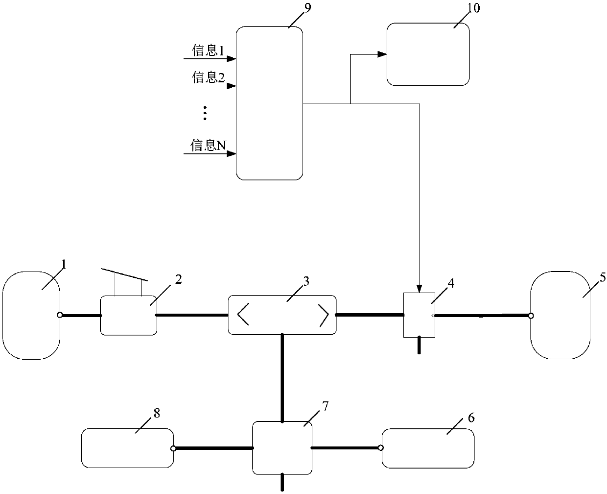
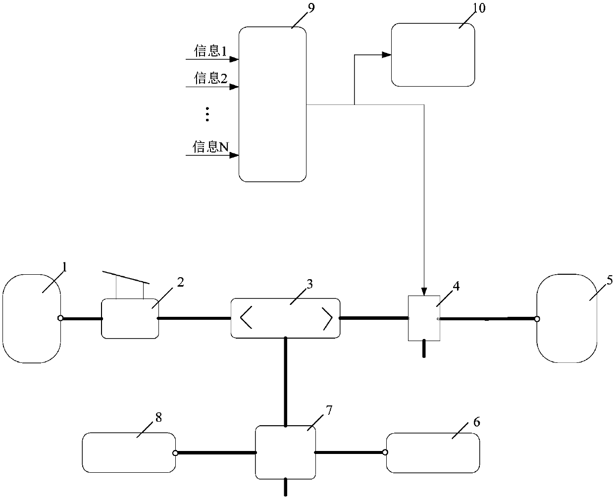
[0017] In order to realize the above parking brake control method, the parking brake system of the present invention is as follows: figure 1 shown. The parking brake system includes: a first air bag 1, a brake pedal 2, a two-way check valve 3, a solenoid valve 4, a second air bag 5, a first brake chamber 6, a quick release valve 7, a second Brake chamber 8, controller 9 and instrument 10. Wherein the controller 9 is connected with the solenoid valve 4 and the instrument 10 through a hard line or a CAN line, the brake pedal 2 and the air outlet of the solenoid valve 4 are respectively connected with the two-way check valve 3, and the two-way check valve 3 is connected with the quick-release valve. 7, and the quick release valve 7 is connected with the first brake chamber 6 and the second brake chamber 8 respectively.

[0018] The first air bag 1 and the second air bag 5 are independent of each other, wherein the first air bag 1 is a service brake air bag, which mainly ensures...

Embodiment 2

[0036] The difference between this embodiment and Embodiment 1 is that the controller in this embodiment also collects the door status signal, and the corresponding judgment logic is: when the vehicle speed is zero and the driver opens the door, the vehicle is controlled to enter the parking brake.

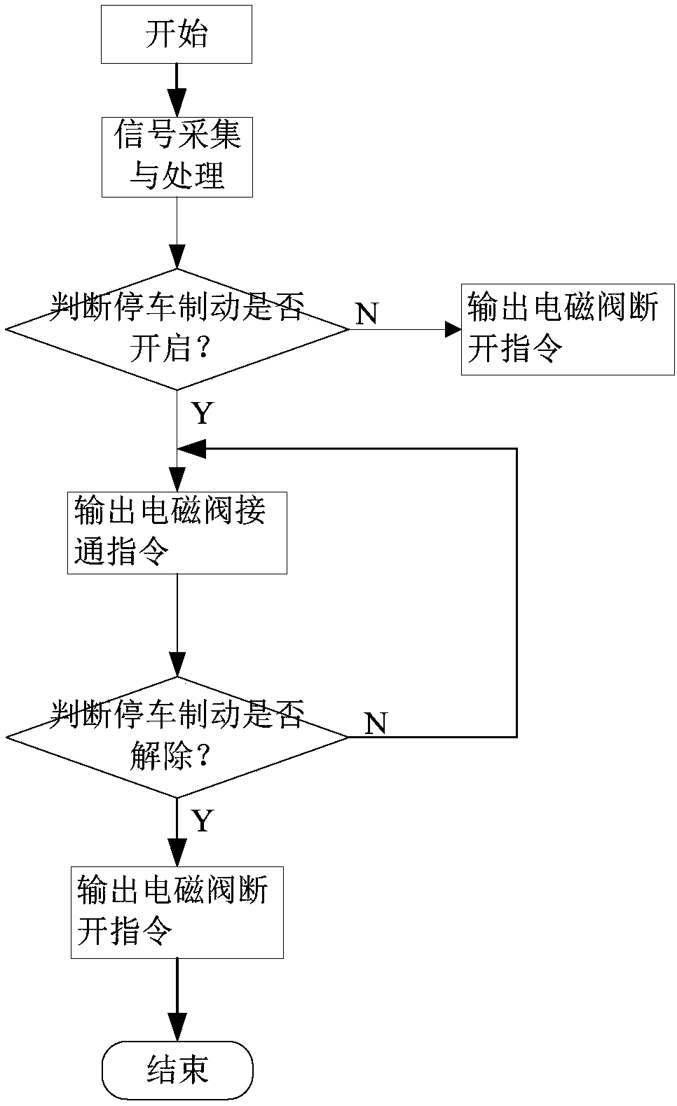
[0037] When the parking brake is turned on, the corresponding ways to determine that the vehicle’s parking brake is released include: a certain time t2 has elapsed, a certain time t3 has elapsed after the driver closes the door, it is detected that the opening of the accelerator pedal is greater than zero, the handbrake is pulled on, and the motor is turned on. The driving torque is greater than the set driving torque value, and the driver operates some kind of button (such as turning on the double flash). In practical applications, any one or more of the above methods can be selected as the determination condition for releasing the parking brake of the vehicle.

[0038] The parki...


PUM


Abstract

The invention relates to a parking brake control method and a system thereof. The parking brake control method comprises the following steps of (1) collecting the vehicle speed and brake pedal openingdegree information of a vehicle; (2) when the vehicle speed is smaller than or equal to the set vehicle speed value, and the brake pedal opening degree is smaller than or equal to the set brake pedalopening degree value, controlling the vehicle to do parking brake; (3) when the vehicle meets the set conditions, relieving the vehicle braking, wherein the set conditions includes the conditions that the set time is passed, or the accelerator pedal opening degree is detected to be greater than zero, or a manual brake is pulled up, or the driving torque of a motor is greater than the set torque value, or a double-flash lamp is turned on. By using the technical scheme, the judgment is performed according to the collected relevant information. If the judging result shows that the vehicle is about to stop or stops, a driver can realize the parking brake without pedaling a brake or pulling up the manual brake; on one hand, the operation intensity of the driver is reduced; on the other hand, the vehicle safety performance is improved.

Description

technical field [0001] The invention relates to a parking braking control method and a system thereof, belonging to the technical field of vehicle braking. Background technique [0002] The driver often encounters temporary parking and long-term parking during driving. To ensure vehicle safety, the driver will always step on the brake or pull on the handbrake, which will increase the labor intensity of the driver and reduce the driving force. In order to improve the safety performance of the vehicle, it is necessary to develop a new braking system or adopt a certain control method to realize the function of temporary parking brake. Contents of the invention [0003] The purpose of the present invention is to provide two parking brake control methods, which are used to solve the problem that the existing brake system and brake control strategy increase the labor intensity of the driver. At the same time, the invention also provides a parking braking system. [0004] To ac...

Claims


Application Information

Patent Timeline
IPC IPC(8): B60W30/18B60W40/105
CPCB60W30/18109B60W40/105B60W2510/083B60W2540/10
Inventor 李高鹏苏常军李涛
Owner ZHENGZHOU YUTONG BUS CO LTD
Learn More