Pole-climbing robot adaptive to diameter of pole

A robot and self-adaptive technology, applied in the fields of motor vehicles, transportation and packaging, etc., can solve the problems of manual work, inability to adapt to the change of rod diameter, poor safety, etc., and achieve the effect of a wide range of application scenarios

Pending Publication Date: 2019-07-02
临颍县爬杆机器人有限公司
View PDF6 Cites 5 Cited by
  • Summary
  • Abstract
  • Description
  • Claims
  • Application Information

AI Technical Summary

Problems solved by technology

[0002] Telephone poles or signal tower tubes are generally tapered rods with a small top and a large bottom. The upper end is erected with wires or installed with other electronic components. In daily work such as power construction, maintenance, etc., it is necessary to continuously climb the pole for related operations. , the traditional way is generally to climb through the foot buckle, the foot buckle method is not only poor in safety but also very inconvenient to operate, and the foot buckle operation cannot realize the automatic delivery of

Method used


Image

  • Pole-climbing robot adaptive to diameter of pole
  • Pole-climbing robot adaptive to diameter of pole
  • Pole-climbing robot adaptive to diameter of pole

Examples


Embodiment 2

[0048] Embodiment 2: The arrangement of the upper and lower rows of the traveling wheel mechanism in this embodiment, each row having two rubber-coated wheels arranged at intervals, is the same as that of the traveling wheel mechanism in Embodiment 1, the difference is that: The structural form of the frame, the structure and arrangement of the telescopic mechanism, and the structure and arrangement of other auxiliary components are all different, and may be common forms in the prior art.

Embodiment 3

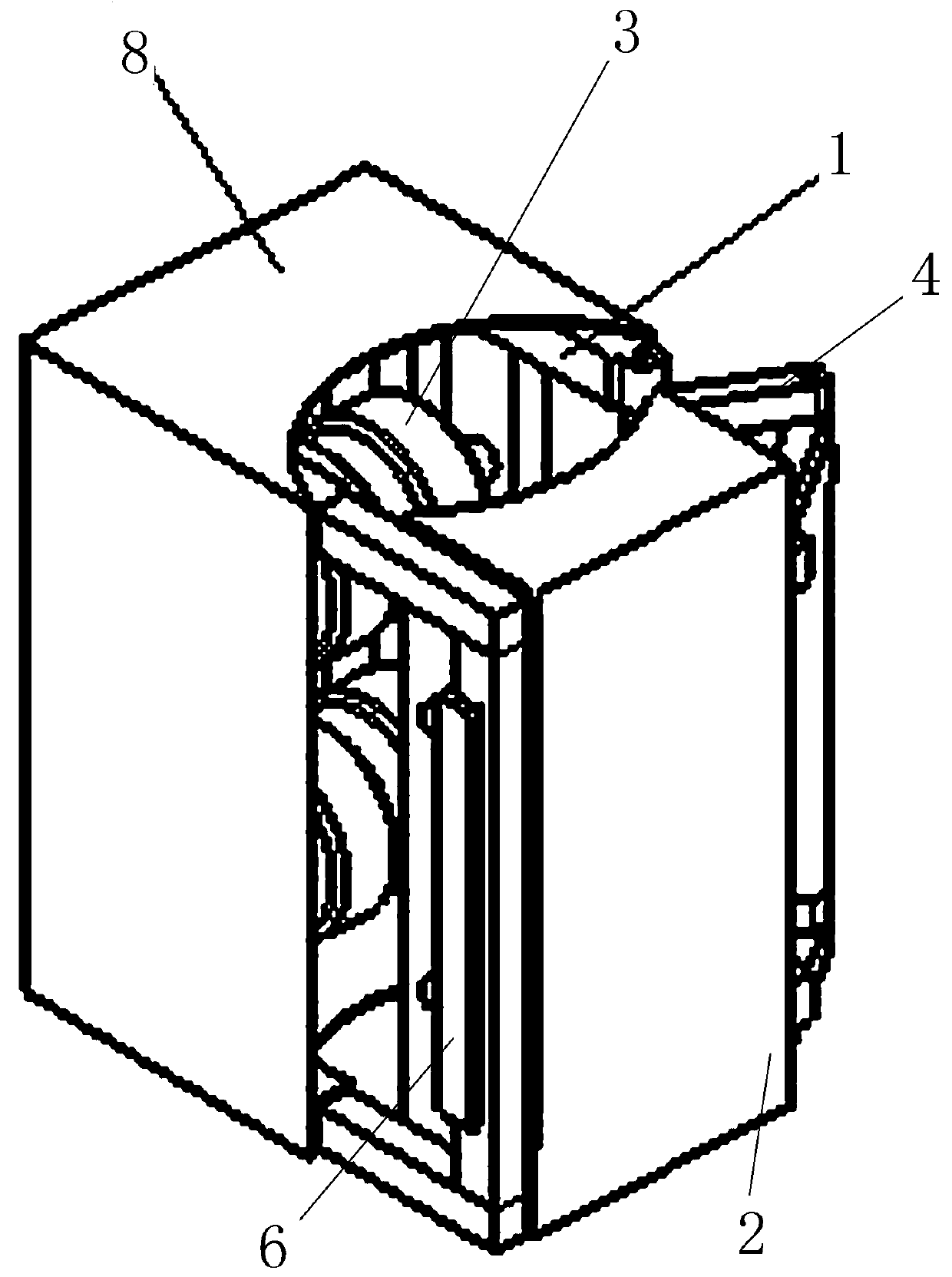
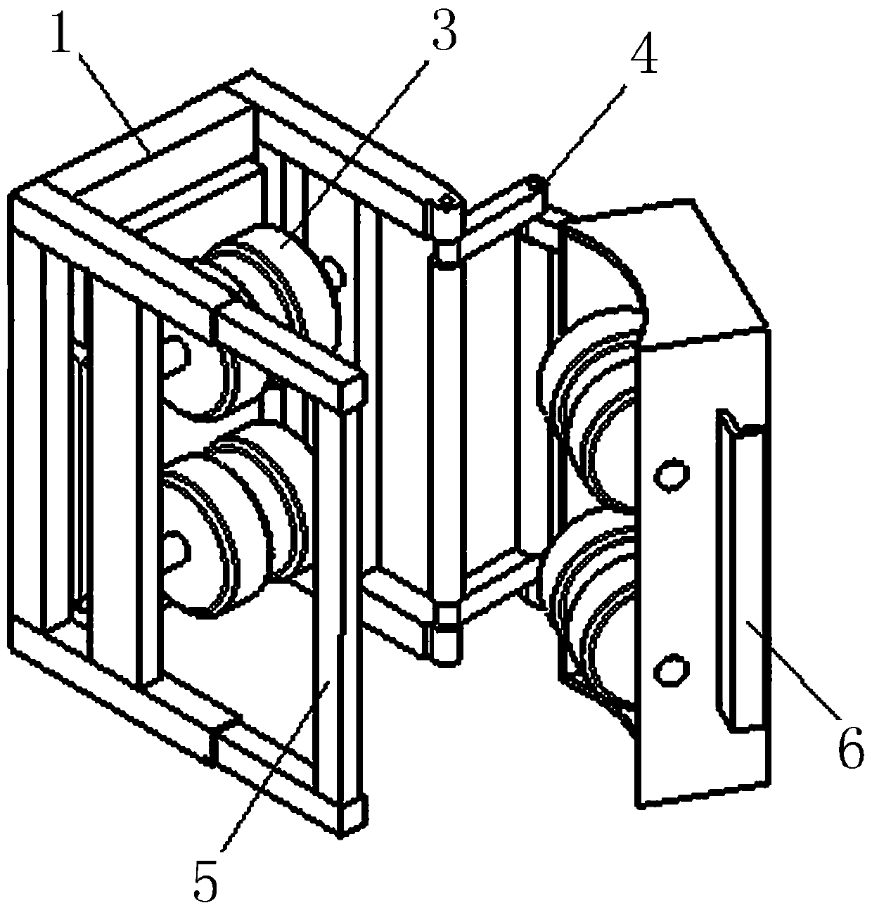
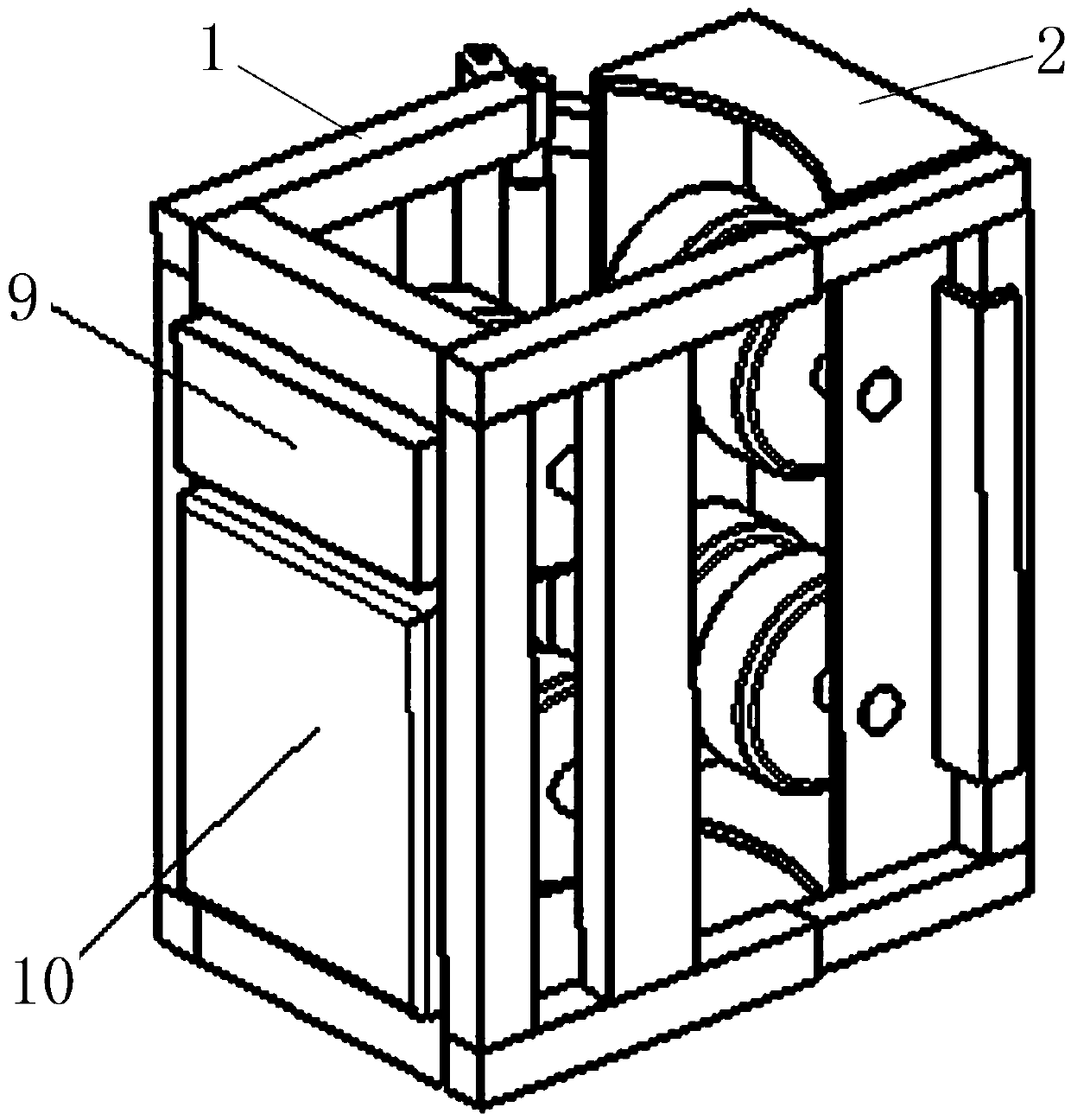
[0049] Embodiment 3: as Figure 6-8 As shown, the difference from Embodiment 1 is that telescopic mechanisms are arranged on both sides of the structure of the two frames, and telescopic springs such as air springs or coil springs are arranged between the telescopic rods, and one end of the telescopic mechanism on one side is connected to the second The two frames are rigidly connected, and the other end is softly connected to the first frame through a hinge 30 (ie, a hinge); one end of the telescopic mechanism on the other side is rigidly connected to the first frame, and the other end is connected to the second frame through an openable buckle structure. The buckle structure is connected, that is, the U-shaped movable hook 5 and the fixed hook 6. The two telescopic mechanisms are respectively rigidly connected with the first frame and the second frame to form an L-shaped frame. The two L-shaped frames are opposite to form a rectangular frame. One connection of the L-shaped f...

Embodiment 4

[0050] Embodiment 4: as Figure 9-11 As shown, the difference from Embodiment 3 is that one side of the two frames is respectively rigidly connected to the two ends of a telescopic rod 31 to form a C-shaped frame, and then a hinge 30 is hinged at the opening of the C-shaped frame. Telescopic rods 31, telescopic springs such as air springs or helical springs are arranged between the telescopic rods, and the other end of the telescopic rods 31 has a gap for the T-shaped hook to connect with the middle of the T-shaped movable hook 5 and the C-shaped frame. The hooking of the fixed hook 6 realizes the detachable connection. The telescopic rod 31 constitutes an I-shaped structure, and the C-shaped structure and the I-shaped structure form a rectangular structure. and separation, this implementation case is a C+I-shaped structure. Of course, the T-shaped movable hook 5 in this embodiment can also be replaced by a rectangular hook or a 7-shaped hook.

[0051] In other embodiments: ...


PUM


Abstract

The invention relates to a pole-climbing robot adaptive to the diameter of a pole. The robot comprises a first frame body and a second frame body. One of the two frame bodies is respectively connectedwith the two sides of the other frame body between the two sides of the walking wheel mechanism of the frame bodies, so that the walking wheel mechanism of the frame bodies are oppositely arranged. Acontaining space is formed between the two walking wheel mechanisms. At least one side of the two frame bodies is provided with an elastic piece which provides an acting force for the two frame bodies in the direction close to each other. The two frames are tensioned through the elastic piece. The walking wheel mechanisms on the two frame bodies are close to each other and enclasp a pole body. During the pole climbing process, along with the change of the diameter of the pole body, a spring automatically stretches out and draws back. Therefore, the automatic adaptation of the robot to the diameter of a to-be-climbed pole body is realized. The robot can be adapted to the regular and irregular change of the diameter of the pole, and the human intervention is not required during the adaptionprocess. The manual control and adjustment of the personnel in the adaption process is not required. The robot automatically adapts to the diameter change of the pole in the pole climbing process. Based on a simple structure, the pole diameter self-adaption function is realized. The robot has a wide application prospect.

Description

technical field [0001] The invention relates to an adaptive rod diameter climbing robot. Background technique [0002] Telephone poles or signal tower tubes are generally tapered rods with a small top and a large bottom. The upper end is erected with wires or installed with other electronic components. In daily work such as power construction, maintenance, etc., it is necessary to continuously climb the pole for related operations. , the traditional way is generally to climb through the foot buckle, the foot buckle method is not only poor in safety but also very inconvenient to operate, and the foot buckle operation cannot automatically transport items to the rod body. [0003] There are also some pole-climbing robots or pole-climbing devices in the prior art. Some of these pole-climbing devices adjust the distance between the walking wheels and the walking wheels in advance when debugging rods with different diameters at the bottom. Manual control mode adjustment, the form...

Claims


Application Information

Patent Timeline
IPC IPC(8): B62D57/024
CPCB62D57/024
Inventor 贾针贾德增
Owner 临颍县爬杆机器人有限公司
Why Eureka
Try Eureka