
Gas heater

A heater and gas technology, applied in the field of heaters, can solve problems such as potential safety hazards, threats to personal safety, large gas flow, etc., and achieve high ignition efficiency and safe ignition process

Inactive Publication Date: 2019-07-02
郑霄
View PDF1 Cites 0 Cited by
  • Summary
  • Abstract
  • Description
  • Claims
  • Application Information

AI Technical Summary

Problems solved by technology

[0003] For example, the utility model with the authorized announcement number CN 202209724U discloses a gas heater, which includes a housing, a gas burner, a gas supply assembly, a gas cylinder and its fixing assembly, and the housing includes a front panel, a door, a side panel, The top plate and the bottom plate, the gas burner is installed on the front plate of the housing through screws, the container assembly includes a gas safety valve with a knob and a connecting air pipe, and the gas supply assembly is arranged between the gas burner and the gas cylinder To form a gas circuit, the gas cylinder is set in the shell and fixed on the bottom plate, and the oxygen deficiency / flame out protection device ODS is installed on the gas circuit. Although this gas heater has a simple structure and is easy to assemble, it also has the following problems: 1. It has only one gas path, and the gas supply and ignition are carried out at the same time. The gas flow during ignition is usually determined by the rotation angle of the shaft, and for different people, the rotation angle is different, so it cannot be well controlled. Small, the gas flow rate is small, and it needs multiple ignitions to ignite, but the rotation angle is too large, the gas flow rate is large, and the fire will be larger immediately after the ignition is successful, which poses a greater threat to personal safety; 2. Because the ODS blocks the long-term The air intake pipe of the open flame takes in air, and after the air intake pipe is blocked, there is still gas between the air intake pipe and the safety valve. Large, there are also security risks

Method used


Image

  • Gas heater
  • Gas heater
  • Gas heater

Examples


Embodiment Construction

[0030] The following are specific embodiments of the present invention and in conjunction with the accompanying drawings, the technical solutions of the present invention are further described, but the present invention is not limited to these embodiments.

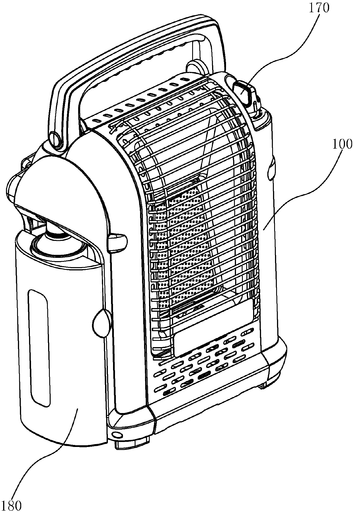
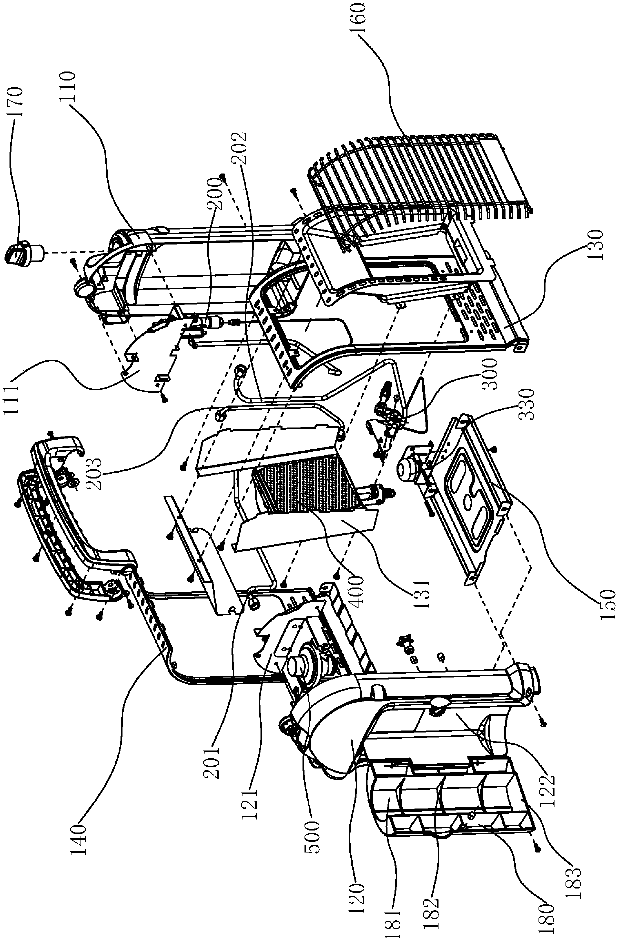
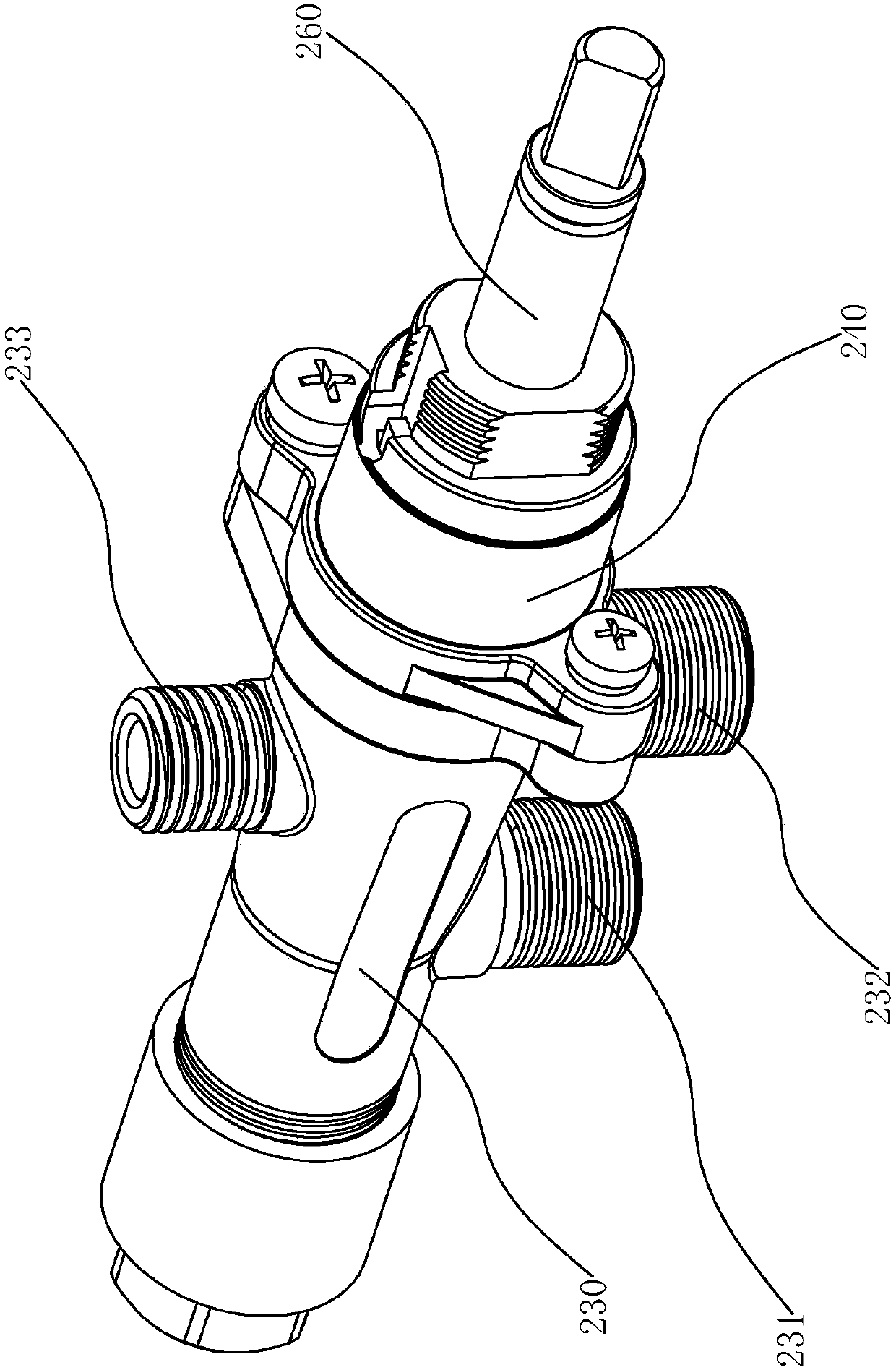
[0031] Such as figure 1 , figure 2 As shown, a gas heater of the present invention includes a casing 100, a control valve 200 arranged in the casing 100 and fixedly connected to the casing 100, an oxygen deficiency protection device 300, and a burner 400. The casing 100 includes a left casing 110 , the right housing 120, the front cover 130 and the rear cover 140 fixedly connected with the left housing 110 and the right housing 120 respectively, and the bottom plate 150 connecting the left housing 110, the right housing 120, the front cover 130 and the rear cover 140, The control valve 200 is installed on the left housing 110 through the first mounting bracket, the burner 400 is fixedly connected to the front cover 130 t...


PUM


Abstract

The invention provides a gas heater, and belongs to the technical field of heaters. The gas heater solves the technical problems that an existing heater is not convenient to use and is not stable andthe use process is not safe. The gas heater comprises a shell, a control valve, an oxygen depletion protection device and a combustor. A gas inlet pipe is connected to the control valve. A gas outletpipe is connected between the control valve and the combustor. The gas inlet pipe and the gas outlet pipe communicate to form a combustion gas way. An ignition gas pipe is connected to the control valve, and the gas outlet end of the ignition gas pipe is opposite to the gas outlet end of the combustor. The gas inlet pipe and the ignition gas pipe communicate to form an ignition gas way. A valve element capable of cutting off gas supply to the combustion gas way during the gas supply time of the ignition gas way is arranged in the control valve. An electromagnetic valve connected with the oxygen depletion protection device and capable of stopping gas inflow of the gas inlet pipe is arranged in the control valve. The ignition gas way and the combustion gas way operates separately. Under thecondition that the ignition gas way is ignited, the ignition success rate of the combustion gas way is high, flow of the combustion gas way is stable, and the ignition process is safe.

Description

technical field [0001] The invention belongs to the technical field of heaters, and relates to a gas heater. Background technique [0002] A heater is a device used for heating. There are many types of heaters, the most common is the electric heater, which uses electricity as energy for heating and heating, and is mostly suitable for indoor use. There is also a gas heater, which uses gas as energy for heating and heating, and is mostly suitable for some wireless The place where the power supply is provided. [0003] For example, the utility model with the authorized announcement number CN 202209724U discloses a gas heater, which includes a housing, a gas burner, a gas supply assembly, a gas cylinder and its fixing assembly, and the housing includes a front panel, a door, a side panel, The top plate and the bottom plate, the gas burner is installed on the front plate of the housing through screws, the container assembly includes a gas safety valve with a knob and a connecti...

Claims


Application Information

Patent Timeline
Patent Type & Authority Applications(China)
IPC IPC(8): F24D15/02F24D19/10
CPCF24D15/02F24D19/1084F24D2200/04
Inventor 郑霄
Owner 郑霄
Learn More