
Flow Control Valves for Burners

A flow control valve and burner technology, applied in valve details, multi-port valves, valve devices, etc., can solve problems such as greater threat to personal safety, inability to control, and inability to control, and achieve ignition Process safety, use safety, and good effect

Active Publication Date: 2017-02-15
NINGBO FIRM TOOLS
View PDF7 Cites 0 Cited by
  • Summary
  • Abstract
  • Description
  • Claims
  • Application Information

AI Technical Summary

Problems solved by technology

[0003] Gas burners often use this flow control valve to control and adjust the gas flow of the burner, and achieve the purpose of igniting the burner or controlling the fire of the burner. The existing flow control valve includes a valve body and a valve body installed in the valve body. The valve core and the rotating shaft, the valve body is provided with an inlet hole and an air outlet hole, and the rotating shaft can adjust the valve core to guide the ignition and adjust the size of the fire. The control valve of this structure is called a two-way type The control valve of this kind of control valve controls the intake air and regulates the gas through a gas flow path at the same time. Although the control valve has a simple structure and is easy to use, it also has the following problems. The gas flow is integrated and synchronized, and the ignition and subsequent gas supply are completed through a gas supply channel. The gas flow during ignition is usually determined by the rotation angle of the shaft, and for different people, the rotation angle is different and cannot be better. If the rotation angle is too small, the gas flow rate is small, and it needs multiple ignitions to ignite, but the rotation angle is too large, the gas flow rate is large, and the fire will be larger immediately after the ignition is successful, which poses a greater threat to personal safety; 2. In use During the process, when the fire is adjusted, especially when the hour is adjusted, because the rotation of the shaft cannot be well grasped, the chamber causes the fire to go out, and after it goes out, it also needs to be ignited again; 3. The burner often pauses briefly during use. For the sake of safety, the burner is generally turned off when it stops. At this time, the unburned gas will be lost, and when it is used again, it needs to be re-ignited, and the gas needs to flow from the gas source to the ignition place again. While wasting gas, its use inconvenient

Method used


Image

  • Flow Control Valves for Burners
  • Flow Control Valves for Burners
  • Flow Control Valves for Burners

Examples


Embodiment Construction

[0029] The following are specific embodiments of the present invention and in conjunction with the accompanying drawings, the technical solutions of the present invention are further described, but the present invention is not limited to these embodiments.

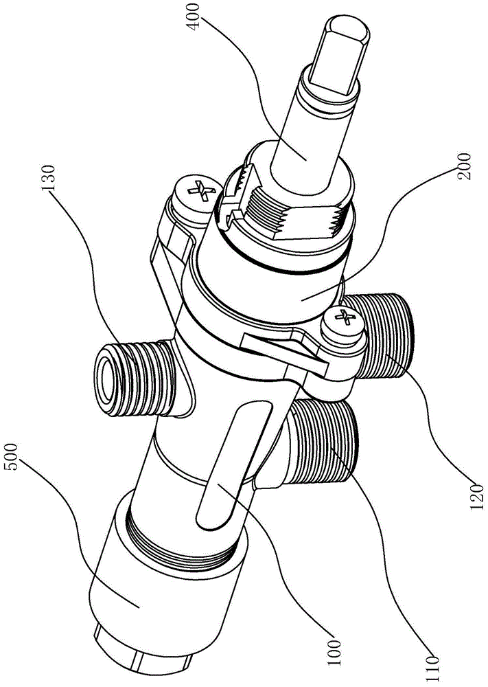
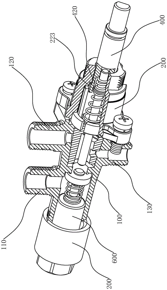
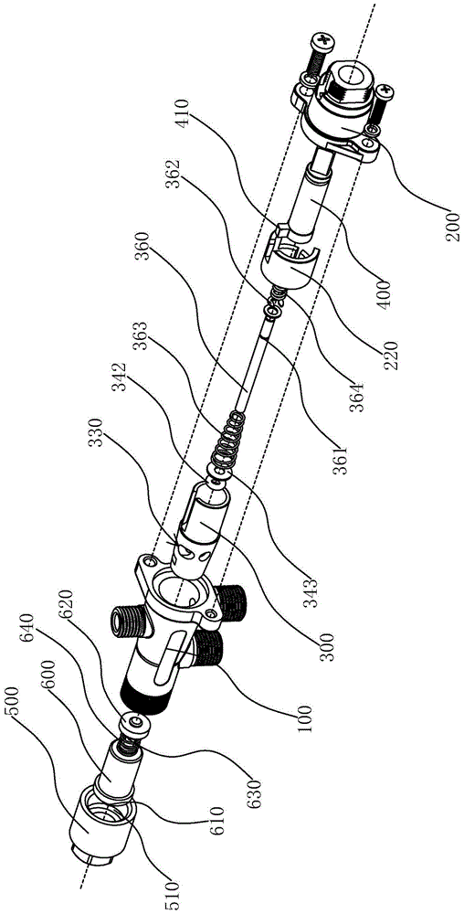
[0030] like figure 1 As shown, the flow control valve used in the burner of the present invention includes a hollow valve body 100 and a front end cover 200 connected with the valve body 100 .

[0031]On the outer surface of the valve body 100, there are axially staggered inlet pipe 110, outlet pipe 120 and pilot gas pipe 130. The pilot gas pipe 130 is located on the outer surface of the valve body 100, and the inlet pipe 110 and the outlet pipe 120 are located opposite to the valve body 100. On the outer surface of one side, the pilot gas pipe 130, the air inlet pipe 110, and the air outlet pipe 120 are respectively arranged on two symmetrical sides of the valve body 100. A spacer 140 is provided to form the first accomm...


PUM


Abstract

The invention provides a flow control valve for a combustor and belongs to the technical field of control valves. The flow control valve is used for solving the technical problems of the existing combustors that gas flow is not easy to control and the use is not safe. The flow control valve for the combustor comprises a valve body and a front end cover, wherein a gas inlet pipe, a gas outlet pipe and a combustion gas introducing pipe are arranged on the external surface of the valve body, a partition block is arranged in the valve body, a first through hole is formed in the partition block, the gas inlet pipe is communicated with a second accommodating chamber, the gas outlet pipe and the combustion gas introducing pipe are respectively communicated with a first accommodating chamber, a valve core is arranged in the first accommodating chamber, an axial hole coaxial with the first through hole is formed in the rear end of the valve core, and a combustion gas introducing hole and a gas outlet hole which are respectively communicated with the axial hole are formed in the external surface of the rear end of the valve core; when the valve core is turned in the first accommodating chamber, the combustion gas introducing pipe is communicated with the combustion gas introducing hole, and the gas outlet pipe is communicated with the gas outlet hole; a combustion gas introducing pipeline and a combusting gas pipeline are subjected to separate gas supplying, and when the combustion gas introducing pipeline is ignited, the gas supply flow is stable, the ignition efficiency is high, and the ignition process is safer.

Description

technical field [0001] The invention belongs to the field of control valve technology, and relates to a flow control valve, in particular to a flow control valve for a burner. Background technique [0002] The flow control valve is a valve that controls the flow of the orifice by changing the liquid resistance of the orifice under a certain pressure difference, thereby adjusting the movement speed of the actuator. It has a wide range of applications and is generally divided into gas flow control valves. with liquid flow control valve. [0003] Gas burners often use this flow control valve to control and adjust the gas flow of the burner, and achieve the purpose of igniting the burner or controlling the fire of the burner. The existing flow control valve includes a valve body and a valve body installed in the valve body. The valve core and the rotating shaft, the valve body is provided with an inlet hole and an air outlet hole, and the rotating shaft can adjust the valve cor...

Claims


Application Information

Patent Timeline
Patent Type & Authority Patents(China)
IPC IPC(8): F16K11/08F16K31/06
CPCF16K11/076
Inventor 张静杰
Owner NINGBO FIRM TOOLS
Learn More