Installation for optical inspection of glass containers at the outlet of a forming machine

A technology for optical inspection and glass containers, which is applied in scientific instruments, optical testing for flaws/defects, and material analysis through optical means, and can solve problems such as high cost, large footprint, and restrictions on installation at the exit of molding machines

Inactive Publication Date: 2019-07-02
TIAMA SOCIETE ANONYME
View PDF9 Cites 0 Cited by
  • Summary
  • Abstract
  • Description
  • Claims
  • Application Information

AI Technical Summary

Problems solved by technology

The light source and the camera are mounted on a frame independent of the transport conveyor structure, because, as stated in the description, it is not conceivable to mount inspection components directly on the conveyor structure due to the high level of vibrations to which the conveyor structure is subjected
However, the high cost of this device and its large footprint on the floor limit the possibility of installing the device at the exit of the forming machine

Method used


Image

  • Installation for optical inspection of glass containers at the outlet of a forming machine
  • Installation for optical inspection of glass containers at the outlet of a forming machine
  • Installation for optical inspection of glass containers at the outlet of a forming machine

Examples


Embodiment Construction

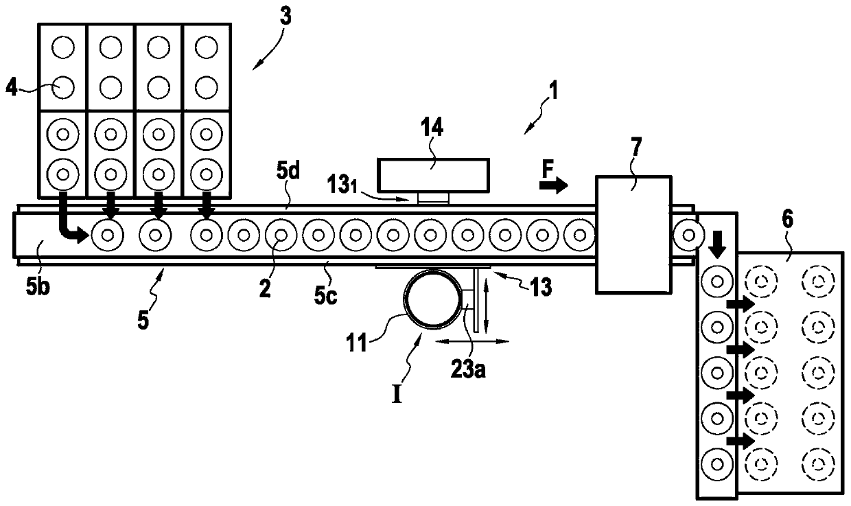
[0030] Such as figure 1 As shown more clearly in , the present invention provides an apparatus 1 which enables transparent or translucent containers 2, such as glass bottles or flasks, to be inspected while the containers are hot. The device 1 is positioned so as to be able to inspect containers 2 leaving a manufacturing or forming machine 3 of any known type. At the exit of the forming machine, the container 2 is at a high temperature, usually in the range of 300°C to 600°C.

[0031] In conventional manner, the forming machine 3 has a series of cavities 4 , each for forming a container 2 . In a known manner, the containers 2 just formed by the machine 3 are successively placed on an outlet conveyor 5 so as to form a row of containers. The containers 2 are transported in rows by a conveyor 5 in a conveying direction F, so as to pass successively through the various processing stations. As usual, the conveyor 5 has a fixed structure 5a standing on the floor S and supporting ...


PUM


Abstract

The invention relates to an installation for optical inspection of containers (2) manufactured by a forming machine at the outlet from which the containers pass, by means of a conveyor (5), in front of at least one inspection device (I) comprising at least one camera (10) mounted in a supporting chamber (11). This installation comprises a system for fastening, to the conveyor (5), the supporting chamber (11) so that this supporting chamber (11) is positioned to one side of the conveyor, having, below the conveyor, a low section (11b) wherein the camera (10) is mounted, the supporting chamber (11) having, above the conveyor, a high section (llh) provided with a viewing window (15) and wherein an optical system for transmission (16) is mounted.

Description

technical field [0001] The invention relates to the technical field of optical inspection of translucent or transparent hollow containers or objects at high temperatures. [0002] The present invention more particularly seeks to provide rapid optical inspection of objects, such as glass bottles or flasks, leaving a manufacturing or forming machine. Accordingly, the present invention seeks to inspect objects in hot regions of manufacturing equipment. Background technique [0003] In a conventional manner, a forming machine is composed of various cavities, each cavity having at least one mold in which the container assumes its final shape at high temperature. At the exit of the forming machine, the containers, still at high temperature, are gripped via the collars of these containers to be moved in order to form a row on the transport conveyor. The spacing between containers can vary and is imposed by the forming machine, depending on the center-to-center distance of the for...

Claims


Application Information

Patent Timeline
IPC IPC(8): G01N21/90
CPCG01N21/9009G01N21/9036G01N2021/9063G01N21/90G01N21/958G01N2201/0438
Inventor A·沙贝尔P·米歇尔C·奥尔蒂斯
Owner TIAMA SOCIETE ANONYME
Why Eureka
Try Eureka