A vacuum blood collection tube centrifuge

A technology of vacuum blood collection tubes and centrifuges, which is applied to centrifuges and other directions, and can solve problems such as high noise and large vibration

Active Publication Date: 2021-03-16
AFFILIATED YONGCHUAN HOSPITAL OF CHONGQING MEDICAL UNIV
View PDF9 Cites 0 Cited by
  • Summary
  • Abstract
  • Description
  • Claims
  • Application Information

AI Technical Summary

Problems solved by technology

[0003] The existing vacuum blood collection tube centrifuges have large vibration and high noise during operation, and the speed and centrifugal force are limited to a certain extent. At the same time, the number and placement direction of the blood collection tubes are also limited. It is required that the vacuum blood collection tubes must be placed symmetrically in an even number Can refer to a kind of vacuum blood collection tube automatic decap centrifuge of publication number C7201410415Y at the same time, its radial outer end is free to hang in the air when its rotating basket frame rotates, when the vacuum blood collection tube quantity that places is placed on each hanging basket is different, also can be in When working, the vibration is large, the noise is high, and the speed and centrifugal force are limited to a certain extent.

Method used


Image

  • A vacuum blood collection tube centrifuge
  • A vacuum blood collection tube centrifuge
  • A vacuum blood collection tube centrifuge

Examples


Embodiment 1

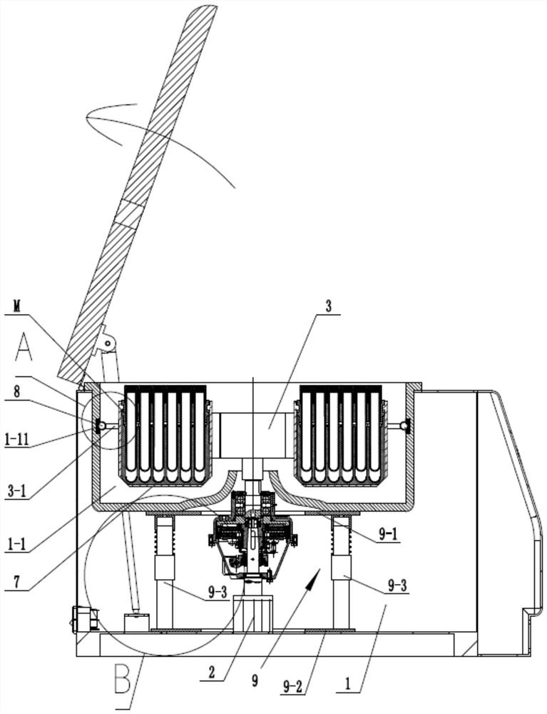
[0045] Embodiment one: see Figure 1-12 , a vacuum blood collection tube centrifuge, including a casing 1, a centrifugal motor 2 and a rotating basket 3.

[0046] The output end of the centrifugal motor 2 is connected with the rotating basket 3 and is used to drive the rotating basket 3 to rotate; the rotating basket 3 is provided with four hanging baskets 7 .

[0047] see Figure 1-4 , The casing 1 is provided with a centrifuge cylinder, the centrifuge cylinder has a centrifuge chamber 1-1 inside, and the rotating basket 3 is located in the centrifuge chamber 1-1.

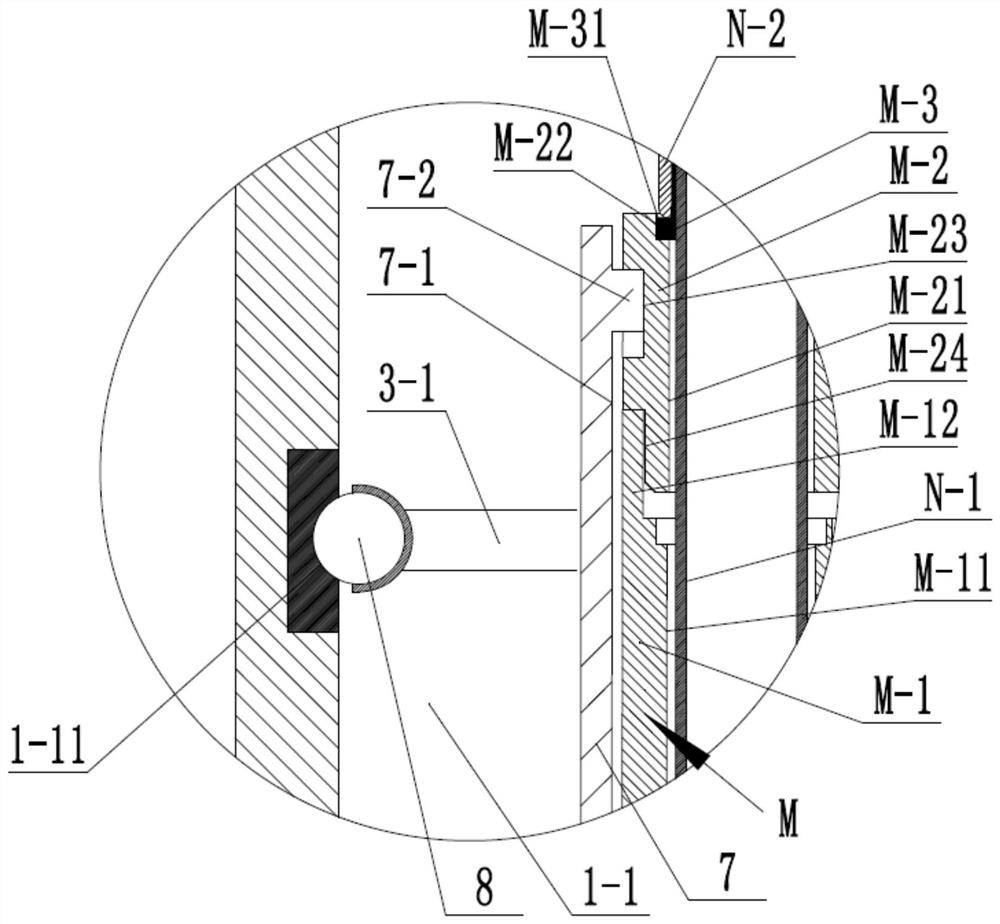
[0048] see Figure 5-6 The rotating basket 3 is fixed with four radial struts 3-1, and the outer end of each radial strut 3-1 is connected to the inner wall of the centrifuge chamber 1-1 by a kinematic pair.

[0049] In the present invention, since the outer ends of a plurality of radial struts 3-1 on the rotating basket 3 are connected to the inner wall of the centrifuge chamber 1-1 by the kinematic pairs, the...

Embodiment 2

[0069] Embodiment 2: This embodiment is basically the same as Example 1, the difference lies in the specific structure of the connection between the outer end of each radial strut 3-1 and the inner wall of the centrifugal chamber 1-1.

[0070] In this example, see Figure 13-14 , the inner wall of the centrifugal chamber 1-1 is fixedly provided with a bearing outer ring 6-1, and the outer end of each radial strut 3-1 is fixedly connected to the bearing inner ring 6-2, and the bearing outer ring 6-1 is connected to the bearing The inner rings 6-2 are connected by rollers 6-3. Since the bearing outer ring 6-1 and the bearing inner ring 6-2 are connected by the roller 6-3, when the bearing outer ring 6-1 and the bearing inner ring 6-2 rotate with each other, the movement process can be reduced. The friction coefficient in the middle, and at the same time ensure its rotation accuracy, it has the advantages of high precision, good rigidity, fatigue resistance, high speed and so on...


PUM


Abstract

The invention discloses a vacuum blood collection tube centrifuge, which comprises a casing (1), a centrifugal motor (2) and a rotating basket frame (3); the output end of the centrifugal motor (2) is connected with the rotating basket frame (3) And it is used to drive the rotating basket (3) to rotate; the rotating basket (3) is provided with a plurality of hanging baskets (7), and it is characterized in that: the casing (1) has a centrifugal chamber (1- 1), and the rotating basket (3) is located in the centrifugal chamber (1-1); the rotating basket (3) is fixed with a plurality of radial struts (3-1), each The outer end of the radial strut (3-1) is connected with the kinematic pair between the inner wall of the centrifugal chamber (1-1). The invention has small vibration and low noise during operation, is more suitable for working conditions of high rotational speed and high centrifugal force, and simultaneously avoids strict restrictions on the number and position of vacuum blood collection tubes.

Description

technical field [0001] The invention belongs to a vacuum blood collection tube centrifuge. Background technique [0002] Medical centrifuges generally refer to vacuum blood collection tube centrifuges in hospital laboratories, blood stations, blood banks, physical examination centers, etc. [0003] The existing vacuum blood collection tube centrifuges have large vibration and high noise during operation, and the speed and centrifugal force are limited to a certain extent. At the same time, the number and placement direction of the blood collection tubes are also limited. It is required that the vacuum blood collection tubes must be placed symmetrically in an even number Can refer to a kind of vacuum blood collection tube automatic decap centrifuge of publication number C7201410415Y at the same time, its radial outer end is free to hang in the air when its rotating basket frame rotates, when the vacuum blood collection tube quantity that there is placed on each hanging basket...

Claims


Application Information

Patent Timeline
Patent Type & Authority Patents(China)
IPC IPC(8): B04B7/00B04B15/00B04B5/04
CPCB04B5/0414B04B7/00B04B15/00B04B9/14
Inventor 邓素容
Owner AFFILIATED YONGCHUAN HOSPITAL OF CHONGQING MEDICAL UNIV
Why Eureka
Try Eureka