Broadband low-RCS antenna based on polarization transformation surface

A polarization conversion and antenna technology, which is applied to antennas, antenna parts, antenna grounding devices, etc., can solve problems such as the inability to achieve antenna scattering effects, and achieve the effect of radar cross-section reduction

Pending Publication Date: 2019-07-05
XIDIAN UNIV +1
View PDF0 Cites 3 Cited by
  • Summary
  • Abstract
  • Description
  • Claims
  • Application Information

AI Technical Summary

Problems solved by technology

In this paper, the strip polarization conversion surface units are arranged in a checkerboard shape around the microstrip antenna. The simulation results show that compared with the reference antenna, the radiation performance of the antenna loaded with the polarization conversion surface is not affected, and the radar cross section is between 10.5- There is an RCS reduction effect greater than 4.8dB in the 35.1GHz frequency band, but only in the three frequency bands of 10.90-13.10GHz, 15.70-19.00GHz and 27.50-33.00GHz, there is an RCS reduction effect greater than 10dB. In 10.5-10.9GHz, 13.1 The RCS reduction effect in the -15.7GHz and 19-27.5GHz frequency bands is less than 10dB, which cannot achieve a good antenna scattering effect

Method used


Image

  • Broadband low-RCS antenna based on polarization transformation surface
  • Broadband low-RCS antenna based on polarization transformation surface
  • Broadband low-RCS antenna based on polarization transformation surface

Examples


Embodiment Construction

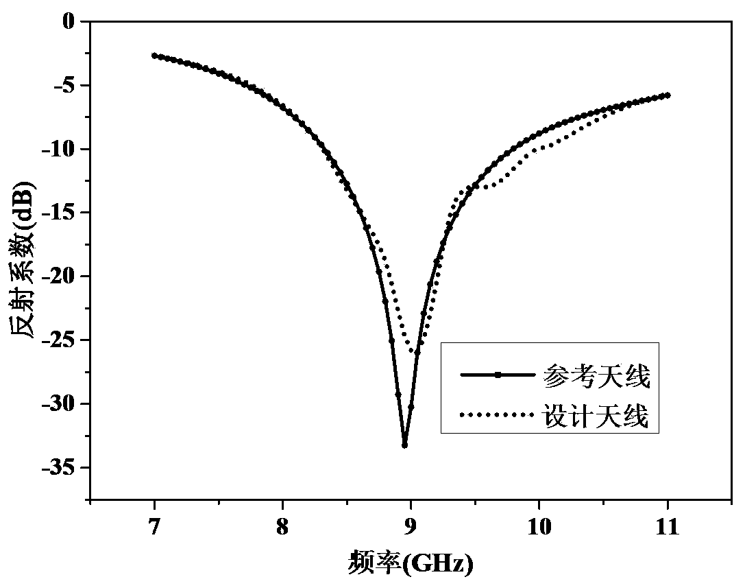
[0020] The specific examples and effects of the present invention will be further described below in conjunction with the accompanying drawings.

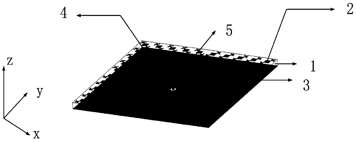
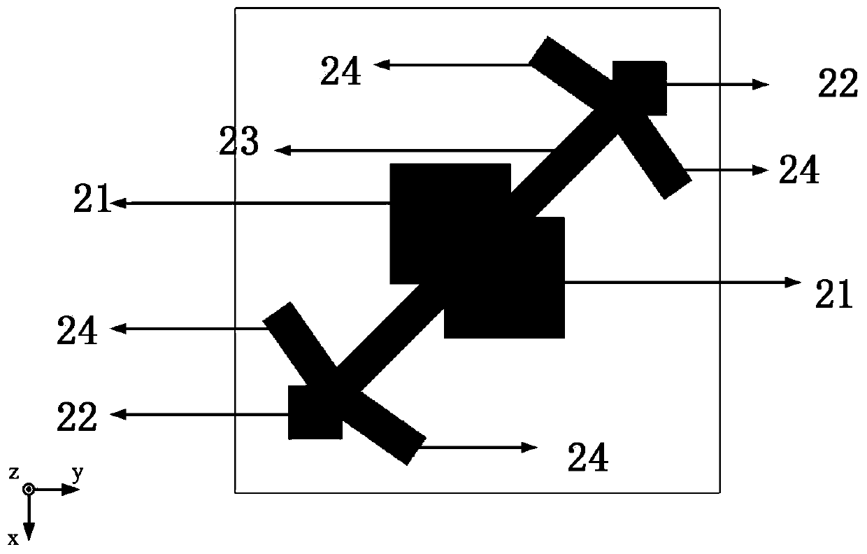
[0021] Reference figure 1 This example includes a dielectric plate 1, a polarization conversion surface 2, a metal floor 3, a metal patch 4, and a coaxial metal column feeder 5. The polarization conversion surface 2 is printed on the dielectric plate 1 in a regular checkerboard pattern. On the periphery of the upper surface, the metal patch 4 is printed on the center of the upper surface of the dielectric board 1, the metal floor 3 is printed on the lower surface of the dielectric board 1, and the coaxial metal column feeder 5 is located 2.4mm from the center of the metal patch 4 . The dielectric plate 1 adopts a rectangular plate of 78mm×78mm×3mm, and its relative permittivity ε'=2.65; the side length c of the metal patch 4 is 8.95mm-9.05mm. This example takes but is not limited to c=9mm. There is a metal through hole in the center o...


PUM


Abstract

The invention discloses a broadband low-RCS antenna based on a polarization transformation surface to mainly solve the serious scattering characteristics of an antenna in the prior art. The broadbandlow-RCS antenna comprises a dielectric board (1), a polarization transformation surface (2), a metal floor (3), a metal patch (4) and a coaxial metal column feeder line (5), wherein the polarization transformation surface and the metal patch are printed on the upper surface of the dielectric board; the metal floor is printed on the lower surface of the dielectric board; the coaxial metal column feeder line is located at a position 2.4mm to the metal patch; the polarization transformation surface (2) is composed of passive resonant polarization transformation units periodically arranged in a M*N checkerboard shape; each polarization transformation unit is composed of two square chip patches (21) at the middle, two square chip patches (22) at the apexes, a strip patch (23) along the diagonal, and four strip patches (24) at the apexes. The broadband low-RCS antenna reduces the radar cross section, improves the scattering effect, and can be used for radar system design with low scatteringcharacteristics.

Description

Technical field [0001] The invention belongs to the technical field of antennas, and particularly relates to a wideband radar cross-section RCS reduced antenna, which can be used for the design of radar systems with low scattering characteristics. Background technique [0002] With the rapid development of communication technology, the radar cross-section reduction technology of antennas has become a hot research topic today. The radar cross-section RCS is a physical quantity that quantitatively measures the antenna's scattering performance. Effective control and reduction of the antenna's RCS has become an important research content for optimizing the design of a radar system with weak scattering performance. [0003] As an important device for transmitting and receiving electromagnetic signals in a radar system, the antenna itself is a structure with strong scattering characteristics. For most radar systems, how to control and reduce the RCS of the antenna has become the key to ...

Claims


Application Information

Patent Timeline
Patent Type & Authority Applications(China)
IPC IPC(8): H01Q15/24H01Q1/48H01Q1/50H01Q1/38H01Q1/24
CPCH01Q1/247H01Q1/38H01Q1/48H01Q1/50H01Q15/242
Inventor 姜文李溪杨博光龚书喜洪涛
Owner XIDIAN UNIV
Why Eureka
Try Eureka