
Synchronous motor double-layer rotor structure

A rotor structure, synchronous motor technology, applied in the magnetic circuit shape/style/structure, electric components, electrical components, etc., can solve the problems of low utilization rate of permanent magnet magnetic circuit, poor heat dissipation capacity of permanent magnet, etc., to improve the output torque , Improve the magnetic utilization rate, improve the effect of heat dissipation conditions

Pending Publication Date: 2019-07-05
SICHUAN UNIV
View PDF8 Cites 1 Cited by
  • Summary
  • Abstract
  • Description
  • Claims
  • Application Information

AI Technical Summary

Problems solved by technology

[0005] In view of this, the object of the present invention is to provide a double-layer rotor structure of a synchronous motor to solve the problems of low utilization rate of the permanent magnet magnetic circuit and poor heat dissipation capacity of the permanent magnet in the prior art

Method used


Image

  • Synchronous motor double-layer rotor structure
  • Synchronous motor double-layer rotor structure
  • Synchronous motor double-layer rotor structure

Examples


Embodiment Construction

[0017] Various embodiments of the invention will be described in more detail below with reference to the accompanying drawings. In the various drawings, the same elements are denoted by the same symbols. For the sake of clarity, various parts in the drawings have not been drawn to scale.

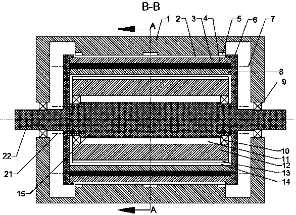
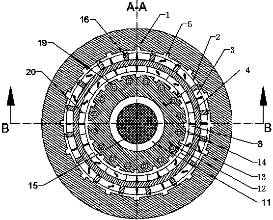
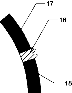
[0018] Such as figure 1 , 2 As shown, the synchronous motor double-layer rotor structure provided by the present invention includes an inner stator (12), an outer stator (1), and a double-layer rotor. The double-layer rotor includes an inner permanent magnet (8), an outer permanent magnet (3), a magnetic isolation material (4), and a wedge-shaped magnetic permeable structure (16). The double-layer rotor is installed between the inner stator (12) and the outer stator (1). The inner permanent magnets (8) and outer permanent magnets (3) of the double-layer rotor are installed with Halbach permanent magnet arrays. The inner and outer permanent magnets are Between the magnets is a magnetic se...


PUM


Abstract

The invention relates to a synchronous motor double-layer rotor structure comprising an inner stator, an outer stator and a double-layer rotor. The double-layer rotor comprisesinner-layer permanent magnets,outer-layer permanent magnets, a magnetic isolating material andwedge-shaped magnetic conductive structures. The double-layer rotor is mounted between the inner stator and the outer stator. Themagnetic isolating material is set between the inner-layer permanent magnet and the outer-layer permanent magnet. The inner-layer permanent magnet and the outer-layer permanent magnet both adoptHalbach arrays. Each wedge-shaped magnetic conductive structure is set between everytwo adjacent outer-layer permanent magnetsof the double-layer rotor. A gap is reserved between every two adjacent inner-layer permanent magnets of the double-layer rotor. Inner and outer layers of the double-layer rotor both adoptHalbach permanent magnet arrays. Magnetic flux density formed by the permanent magnets is centralized to oneside of an air gap, so output torque of a motor is improved. Through setting of the wedge-shaped magnetic conductive structures among the outer-layer permanent magnets, magnetic induction lines of the permanent magnet are prompted to form a loop at an outer air gap, so the magnetic induction lines pass through the outer air gap to the greatest extent, and a magnetic utilization rate is improved. Through reservation of the gap between the two adjacent pieces of inner-layer permanent magnet, a heat dissipation condition of the permanent magnet can be improved.

Description

technical field [0001] The invention relates to a motor, in particular to a double-layer rotor structure of a synchronous motor. Background technique [0002] With the rapid development of electric vehicles, people's requirements for motor power density are also getting higher and higher. On the premise of not increasing the volume and quality of the motor, how to increase the output power of the motor is attracting increasing attention. The traditional motor structure often cannot meet the requirements. The double-layer rotor synchronous motor can greatly increase the motor output power without changing the quality. Increasing the output torque of the motor and increasing the output power of the motor have attracted more and more attention from motor manufacturers and researchers. [0003] In the existing technical solutions, the permanent magnets are generally attached to the rotor core or embedded in the rotor core in the dual-rotor motor. On the basis of considering the...

Claims


Application Information

Patent Timeline
Patent Type & Authority Applications(China)
IPC IPC(8): H02K16/04H02K1/27H02K1/32
CPCH02K16/04H02K1/2773H02K1/2786H02K1/325
Inventor 魏文龙袁靖唐斯琪姚进刘伟熊志强
Owner SICHUAN UNIV
Learn More