
Three-phase separation stator yoke-free modularized axial magnetic flux permanent magnet disc type wheel hub direct-driven motor

A wheel-hub direct-drive motor, three-phase separation technology, applied to synchronous motors with stationary armatures and rotating magnets, magnetic circuit shape/style/structure, magnetic circuit, etc., to reduce space occupation, improve efficiency, reduce The effect of surface temperature

Inactive Publication Date: 2019-07-05
HARBIN UNIV OF SCI & TECH
View PDF4 Cites 1 Cited by
  • Summary
  • Abstract
  • Description
  • Claims
  • Application Information

AI Technical Summary

Problems solved by technology

[0005] The purpose of the present invention is to solve the problems existing in the current wheel hub motor, and to provide a three-phase separated stator yokeless modular axial flux permanent disk type wheel hub direct drive motor

Method used


Image

  • Three-phase separation stator yoke-free modularized axial magnetic flux permanent magnet disc type wheel hub direct-driven motor
  • Three-phase separation stator yoke-free modularized axial magnetic flux permanent magnet disc type wheel hub direct-driven motor
  • Three-phase separation stator yoke-free modularized axial magnetic flux permanent magnet disc type wheel hub direct-driven motor

Examples


Embodiment Construction

[0028] The implementation of the present invention will be described in detail below in conjunction with the accompanying drawings and examples, so as to fully understand and implement the process of how to apply technical means to solve technical problems and achieve technical effects in the present invention. It should be noted that, as long as there is no conflict, each embodiment and each feature in each embodiment of the present invention can be combined with each other, and the formed technical solutions are all within the protection scope of the present invention.

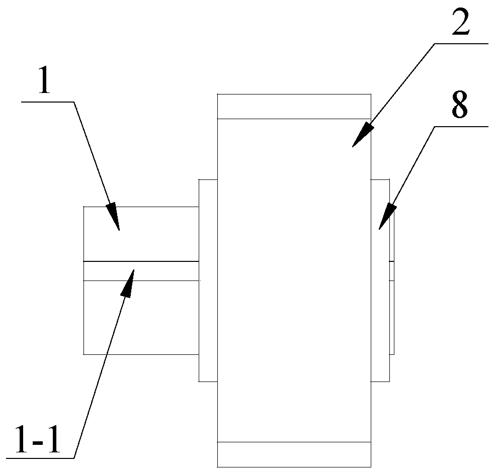
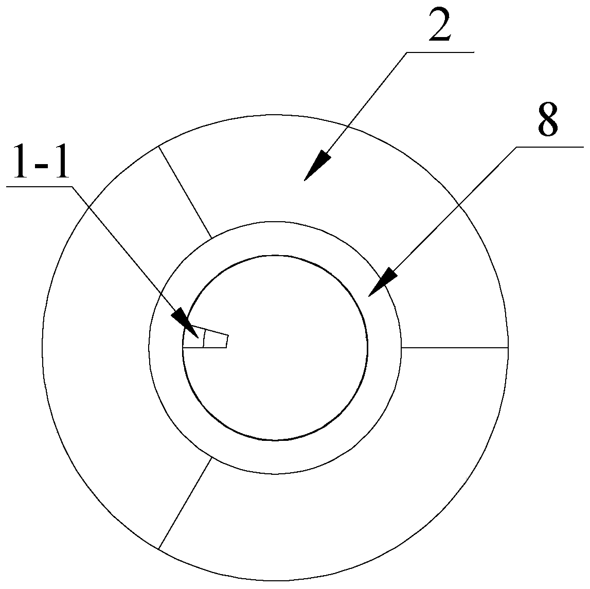
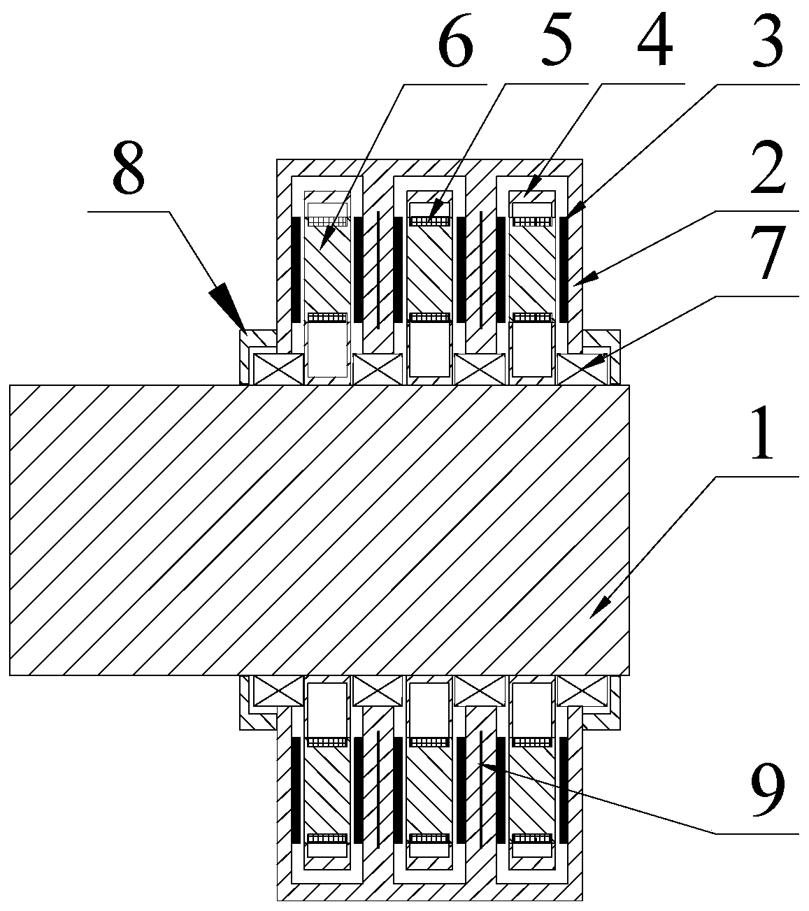
[0029] see Figure 1 to Figure 11 , the three-phase separated stator yokeless modular axial flux permanent disk hub direct drive motor in this embodiment includes an outer rotor, an inner stator and a fixed shaft 1, the inner stator is fixedly arranged on the fixed shaft 1, and the inner stator is arranged on the outer The inside of the rotor, and there is an air gap between the two, and the rotation connect...


PUM


Abstract

The invention discloses a three-phase separation stator yoke-free modularized axial magnetic flux permanent magnet disc type wheel hub direct-driven motor, and belongs to the field of brushless direct-current motors. The problem of an existing wheel hub motor is solved. The three-phase separation stator yoke-free modularized axial magnetic flux permanent magnet disc type wheel hub direct-driven motor comprises an outer rotor, an inner stator and a fixed shaft, wherein three groups of stator supports of the inner stator are arranged on the fixed shaft in parallel; 2p iron core mounting holes are uniformly formed in the stator support in the circumferential direction and are used for mounting a stator iron core module which enwinds a stator winding 5; a rotor support of the outer rotor is provided with a rotor connecting outer tube and four circular ring rotor back irons, so that three annular chamber areas are formed; a group of stator supports is accommodated in each of the annular chamber areas; 4p permanent magnets are uniformly arranged on the two inner end faces of each of the annular areas; the permanent magnets are magnetized in the axial direction, the magnetized directionsof the two adjacent permanent magnets on the same end face are opposite to each other, and the magnetized directions of the permanent magnets which are arranged in the same annular chamber and positioned on the two end faces are opposite, and the permanent magnets of the three annular chambers are distributed sequentially at different electrical angles of 120 degrees in the circumferential directions.

Description

technical field [0001] The invention belongs to the field of brushless DC motors. Background technique [0002] Energy and environmental protection are major problems facing the development of the world today. Electric vehicles are gradually recognized by the market due to their zero emissions and environmental friendliness. Most of the electric drive systems used by electric vehicles on the market today mainly adopt centralized The drive system is similar to traditional gasoline and diesel engines. The drive motor is placed on the front or rear of the chassis of the car, and the power is transmitted to each wheel through the drive shaft. The hub motor can flexibly arrange the drive system on the The drive wheel of the car is ingeniously integrated with the wheel, and can independently control each wheel hub motor, so that the system control efficiency can be effectively improved. [0003] With the continuous progress of the design, the hub motor of the conventional permane...

Claims


Application Information

Patent Timeline
Patent Type & Authority Applications(China)
IPC IPC(8): H02K21/24H02K1/27H02K1/30H02K1/18
CPCH02K1/182H02K1/2793H02K1/30H02K21/24
Inventor 谢颖宁召阳马泽新胡圣明
Owner HARBIN UNIV OF SCI & TECH
Learn More