High-pressure separator

A technology of high-pressure separator and sloping plate, which is applied in the direction of separation method, sedimentation separation, chemical instrument and method, etc. It can solve the problems of reduced efficiency of liquid flowing into the separator, increase of water surface fluctuation, and aggravated pipeline blockage, etc., so as to achieve stable connection, The effect of calming the water flow and increasing the buffer strength

Active Publication Date: 2019-07-09
山西盛达威科技有限公司
View PDF11 Cites 1 Cited by
  • Summary
  • Abstract
  • Description
  • Claims
  • Application Information

AI Technical Summary

Problems solved by technology

[0003] The working principle of the existing high-pressure separator is as follows: Figure 5 As mentioned above, the gas-liquid mixed fluid enters the separator through the gas-liquid inlet for basic phase separation, the gas enters the gas channel for gravity sedimentation to separate droplets, the liquid enters the liquid space to separate bubbles and solid impurities, and the gas is captured before leaving the separator. After the mist removes small droplets, it flows out from the air outlet, and the liquid flows out from the liquid outlet. When the liquid enters the separator again, the liquid will hit the baffle 11 instantly. When the traditional separator is in use, the baffle is hit by the liquid , a part of the liquid is backflowed by force, causing the impacted liquid to meet and mix with the newly injected liquid, resulting in a decrease in the efficiency of the liquid flowing into the separator, and during the reinjection of the liquid, the water flow will stir the liquid in the separator, resulting in The sediment in the separator is impacted and surged, and enters the pipeline with the water flow, causing the pipeline to be blocked. At the same time, after the baffle is used for a period of time, it is subjected to a strong impact, and the baffle falls off the separator, resulting in the buffering of the liquid being affected. Influenced by the increase of water surface fluctuations, further aggravating the clogging of pipelines, resulting in more water in the oil layer

Method used


Image

  • High-pressure separator
  • High-pressure separator
  • High-pressure separator

Examples


Embodiment Construction

[0018] The following will clearly and completely describe the technical solutions in the embodiments of the present invention with reference to the accompanying drawings in the embodiments of the present invention. Obviously, the described embodiments are only some, not all, embodiments of the present invention. Based on the embodiments of the present invention, all other embodiments obtained by persons of ordinary skill in the art without making creative efforts belong to the protection scope of the present invention.

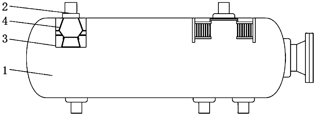
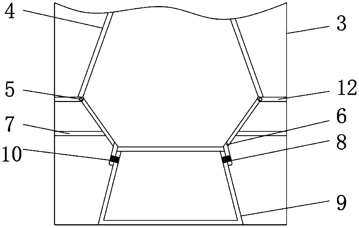
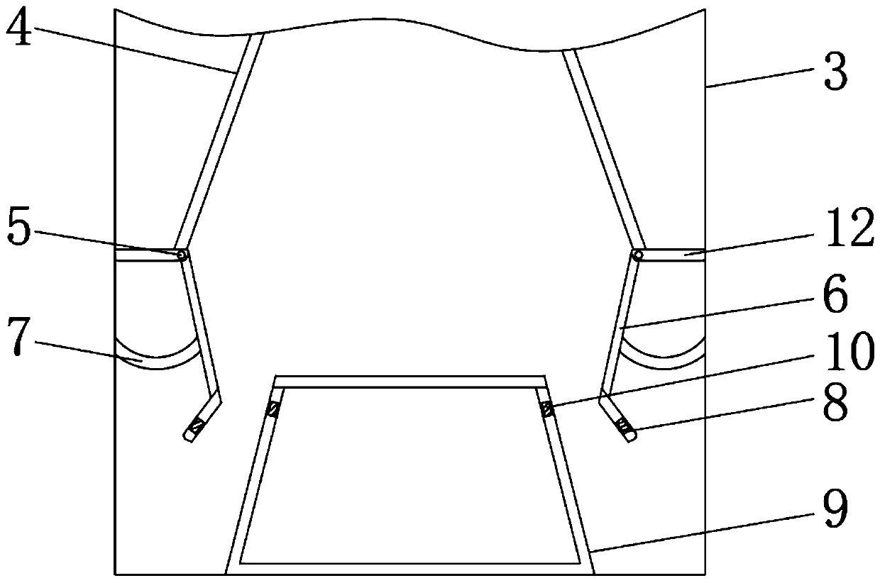
[0019] see Figure 1-4 , a high-pressure separator, including a tank body 1, a feed pipe 2, the feed pipe 2 is installed on the top of the tank body 1, a ferrule 3 is installed in the tank body 1, the ferrule 3 is rectangular, and the ferrule 3 is installed The deflector 4 is arranged, and the deflector is in an inverted conical shape, which is convenient for the diffusion of the water flow, so that the area after the flow of the water flow becomes larger, and...


PUM


Abstract

The invention relates to the technical field of intelligent production, and discloses a high-pressure separator. The high-pressure separator comprises a tank and a feeding pipe, wherein the feeding pipe is installed on the top of the tank, a clamping sleeve is installed in the tank, a diversion plate is installed in the clamping sleeve, a positioning board located on the bottom of the diversion plate is installed in the clamping sleeve, a sliding rod is installed on an end portion of the positioning board, and a sloping board is installed on the sliding rod. According to the high-pressure separator, by changing fixed connection of a traditional baffle into elastic connection, when liquid runs through the feeding pipe, by means of impact force, the clamping sleeve conducts self-adaption adjustment, when a water flow is large, connection between the sloping board and the diversion pipe is cut by the impact force, thus a drain opening of the water flow is transformed into three drain openings, and strength of the water flow during flowing is greatly improved; and by designing elastic connection, buffering strength of the water flow is improved furthest, so that the water flow in the tank calms down, the liquid can be conveniently separated, and meanwhile, the liquid is in an excellent state when separated.

Description

technical field [0001] The invention relates to the technical field of intelligent manufacturing, in particular to a high-pressure separator. Background technique [0002] A separator is a machine that separates a mixed substance into two or more different substances. [0003] The working principle of the existing high-pressure separator is as follows: Figure 5 As mentioned above, the gas-liquid mixed fluid enters the separator through the gas-liquid inlet for basic phase separation, the gas enters the gas channel for gravity sedimentation to separate droplets, the liquid enters the liquid space to separate bubbles and solid impurities, and the gas is captured before leaving the separator. After the mist removes small droplets, it flows out from the air outlet, and the liquid flows out from the liquid outlet. When the liquid enters the separator again, the liquid will hit the baffle 11 instantly. When the traditional separator is in use, the baffle is hit by the liquid , a...

Claims


Application Information

Patent Timeline
Patent Type & Authority Applications(China)
IPC IPC(8): B01D19/00B01D21/00B01D21/24
CPCB01D19/00B01D21/00B01D21/2444
Inventor 胡军辉
Owner 山西盛达威科技有限公司
Why Eureka
Try Eureka