Connection-wing-configuration novel vertical-take-off-and-landing unmanned aerial vehicle
A technology for vertical take-off and landing of drones, applied in the field of drones, which can solve problems such as large load capacity, low load capacity, and short battery life
- Summary
- Abstract
- Description
- Claims
- Application Information
AI Technical Summary
Problems solved by technology
Method used
Image
Examples
Embodiment 2
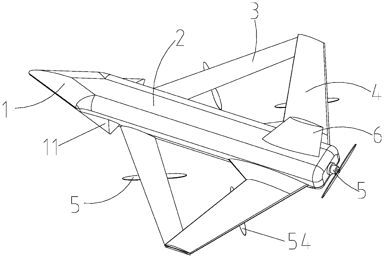
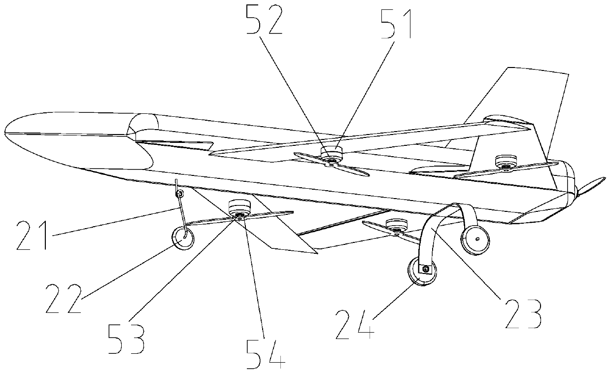
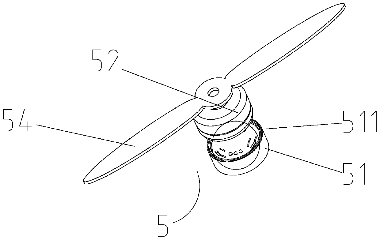
[0058] In the figure, the same reference numerals as those used in the above-mentioned embodiments still follow the definition of the reference numerals in the above-mentioned embodiments.
[0059] The newly appearing reference signs are defined as follows: 25, umbrella cabin; 251, second pin hole; 252, supporting plate; 253, spring; 26, hatch door; 261, first pin hole; 27, steering gear; 271, rocking Arm; 272, latch; 28, parachute; 281, parachute; 29, hanging point.
[0060] see Figure 6 to Figure 7 The difference between this embodiment and Embodiment 1 is that: the upper end of the fuselage 2 is provided with an umbrella cabin 25, the upper end of the umbrella cabin 25 has an opening, and the opening 511 of the umbrella cabin 25 is hinged with one end of the hatch door 26 , the other end of the hatch 26 is provided with a first pin hole 261, the inside of the fuselage 2 is provided with a second pin hole 251 corresponding to the first pin hole 261, and the inside of the f...
Embodiment 3
[0069] In the figure, the same reference numerals as those used in the above-mentioned embodiments still follow the definition of the reference numerals in the above-mentioned embodiments.
[0070] Newly occurring reference signs are defined as follows: 7. Swept wing.
[0071] see Figure 8 and Figure 9 , The difference between this embodiment and Embodiment 2 is that: the wingtips of the two front wings 3 are symmetrically connected with a swept wing 7 .
[0072] The set swept wing 7 can increase the lift and stability of the fuselage 2. In addition, it can also increase the load capacity and increase the flight speed, making the application scenarios of the swept wing 7 more abundant. Here, the front wing 3 can Corresponding pins and pin holes are set at the wing tip of the wing tip and the wing root of the swept wing 7, by inserting the pin into the pin hole, then inserting it into the pin hole through the top wire, and tightening the pin, so that the front wing 3 Faste...
Embodiment 4
[0074] In the figure, the same reference numerals as those used in the above-mentioned embodiments still follow the definition of the reference numerals in the above-mentioned embodiments.
[0075] Newly occurring reference signs are defined as follows: 8, straight wing.
[0076] see Figure 10 , this embodiment and image 3 The difference is that the swept wing 7 is replaced by a straight wing 8 in this embodiment.
[0077]The set straight wing 8 can increase the lift of the fuselage 2 to increase the load, making the application scenarios of the straight wing 8 more abundant. Here, corresponding pins can be set on the wing tip of the front wing 3 and the wing root of the straight wing 8 and the pin hole, by inserting the bolt into the pin hole, then inserting it into the pin hole through the top wire, and tightening the bolt, so that the front wing 3 and the straight wing 8 are fastened and spliced. This method of quick loading and unloading of Wing 8 effectively improves...
PUM
 Abstract
Description
Claims
Application Information
 - R&D
- Intellectual Property
- Life Sciences
- Materials
- Tech Scout
- Unparalleled Data Quality
- Higher Quality Content
- 60% Fewer Hallucinations
Browse by: Latest US Patents, China's latest patents, Technical Efficacy Thesaurus, Application Domain, Technology Topic, Popular Technical Reports.
© 2025 PatSnap. All rights reserved.Legal|Privacy policy|Modern Slavery Act Transparency Statement|Sitemap|About US| Contact US: help@patsnap.com


