Electric moving trolley used for steering test table

A technology of steering test and mobile trolley, which is applied in the direction of hoisting device, lifting frame, manual conveying device, etc., which can solve the problems of difficult lifting height precision control, labor-intensive, and low practicability, and achieve manpower saving, convenient operation, and practicability strong effect

Active Publication Date: 2019-07-09
NANJING INST OF TECH
View PDF4 Cites 0 Cited by
  • Summary
  • Abstract
  • Description
  • Claims
  • Application Information

AI Technical Summary

Problems solved by technology

The traditional mobile trolley is a scissor lift trolley, which adopts a scissor structure for lifting, but the scissor lift trolley needs manpower to drive, which consumes manpower, is inconvenient to move, and is difficult to precisely control the lifting height, and has low practicability

Method used


Image

  • Electric moving trolley used for steering test table
  • Electric moving trolley used for steering test table
  • Electric moving trolley used for steering test table

Examples


Embodiment 1

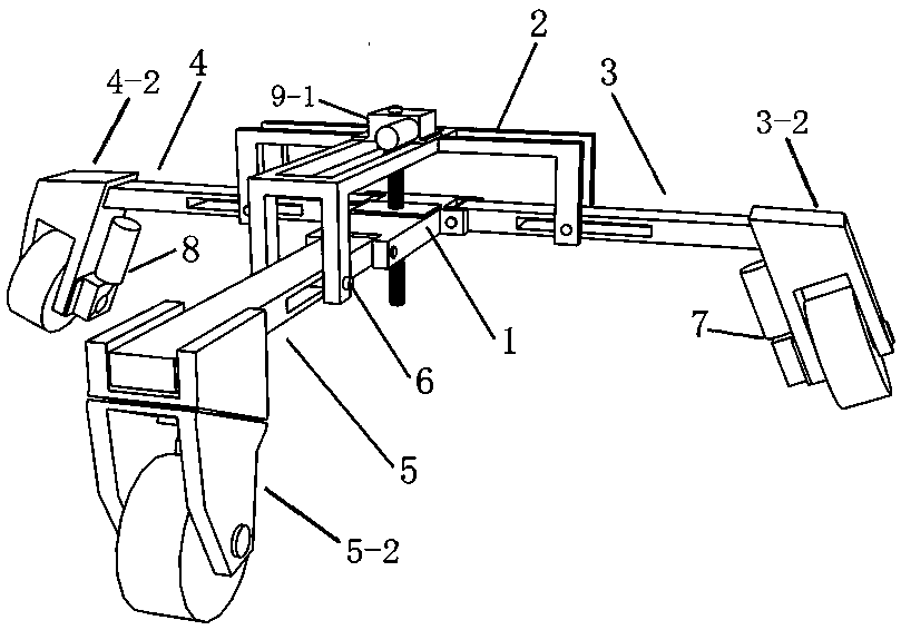
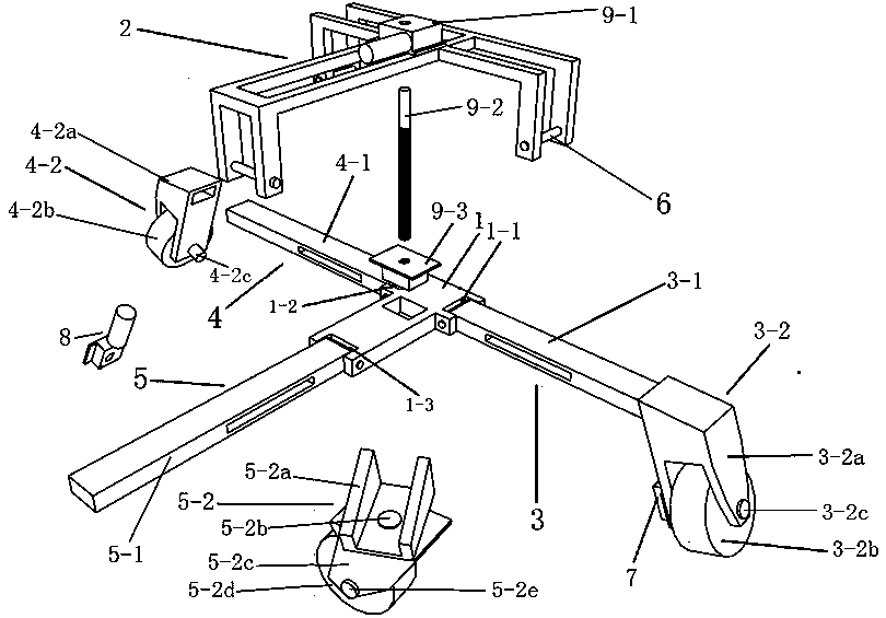
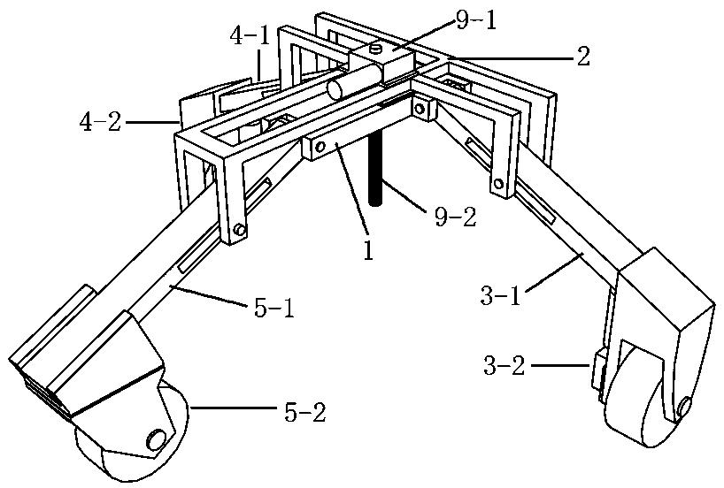
[0039] Embodiment one: if Figure 3-7 As shown, when the test table hollowed out at the bottom needs to be moved, the drive controller remotely controls the lifting hollow shaft reduction motor 9-1 to drive the lifting screw 9-2 to rotate forward, and the lifting screw 9-2 drives the lifting nut 9-3 through the screw. , so that the lifting platform 1 makes a downward movement along the lifting screw 9-2, and drives the left bracket 3-1, the right bracket 4-1 and the front bracket 5-1 to move around the pin 6 on the three claws of the lifting adjustment bracket 2 to seesaw respectively , and then drive the left drive wheel 3-2, the right drive wheel 4-2 and the front universal wheel 5-2 to rise synchronously, and when the three wheels rise to the bottom of the test table, the drive controller controls the lifting screw 9 -2 Stop the rotation, and control the left hollow shaft deceleration motor 7 and the right hollow shaft deceleration motor 8 to respectively drive the left dri...

Embodiment 2

[0040] Embodiment two: if Figure 5-7 As shown, the electric mobile trolley for the above-mentioned steerable test table is fixed on the bottom surface of the existing test table through the lifting adjustment bracket 2, and can be used as a table leg. When the test table needs to be moved, the upgraded version of the test table can be controlled by driving The driver drives the mobile trolley to move in all directions and shift. When it does not need to move, the drive controller can drive the left drive wheel 3-2, the right drive wheel 4-2 and the front universal wheel 5-2 to rise synchronously and store them at the bottom of the table. Easy to operate and save manpower.


PUM


Abstract

The invention discloses an electric moving trolley used for a steering test table. A running mechanism is fixed to a lifting platform and is driven by a running driving mechanism to conduct running and steering. A lifting adjusting support is movably connected with the running mechanism. A lifting driving mechanism drives the lifting platform to drive the running mechanism to do lifting motion. Adriving controller remotely controls and drives the running driving mechanism and the lifting driving mechanism. By means of the electric moving trolley, a universal wheel is adopted as the front wheel, the driving controller is used for controlling a left driving wheel and a right driving wheel to move forwards or backwards in a wire control manner or a remote control manner, all-dimensional steering and moving of the moving trolley can be achieved, the lifting height can be accurately controlled by controlling rotation stopping of a lifting screw rod, operation is convenient, the applicationrange is wide, electric control moving is achieved, and labor is saved; a lifting hollow-shaft speed reduction motor can be used for synchronously lifting the three wheels by driving screw transmission between the lifting screw rod and a lifting nut, and a to-be-carried object can be supported or storage space is collected; and the moving trolley is fixed to the bottom face of the test table to serve as a table leg, remote control moving can be achieved, and practicability is high.

Description

technical field [0001] The invention belongs to the technical field of handling machinery, and in particular relates to an electric moving trolley for a test table that can be steered. Background technique [0002] As a common handling tool, the mobile trolley is widely used in the handling of small equipment such as household appliances and test tables. The traditional mobile trolley is a scissor lift trolley, which uses a scissor structure for lifting, but the scissor lift trolley needs manpower to drive, which consumes manpower, is inconvenient to move, and is difficult to precisely control the lifting height, and has low practicability. Contents of the invention [0003] The technical problem to be solved by the present invention is to provide an electric mobile trolley for a steerable test table that can be moved by all-round electric control, easy to operate, precise in height adjustment, and occupies a small space. [0004] In order to achieve the above technical p...

Claims


Application Information

Patent Timeline
IPC IPC(8): B66F7/06B66F7/28B65G7/04
CPCB65G7/04B66F7/0608B66F7/0625B66F7/28
Inventor 张敏黄辉祥王泽坤石爱峰陈振波
Owner NANJING INST OF TECH
Why Eureka
Try Eureka