Jump ring type self-locking anti-loose connector

A technology of electrical connectors and circlips, applied in connection, two-part connection devices, parts of connection devices, etc., can solve problems such as complex product structure, increased manufacturing costs, and loose locking, and achieve consistent performance of parts Good, extended service life, low production cost

Pending Publication Date: 2019-07-09
CHINA NORTH IND GRP HANGLIAN TECH CO LTD
View PDF0 Cites 0 Cited by
  • Summary
  • Abstract
  • Description
  • Claims
  • Application Information

AI Technical Summary

Problems solved by technology

[0002] The locking methods of traditional electrical connectors can generally be divided into the following types: 1. Bayonet type. The locking force after mating is maintained by the pressure generated by the spring. The disadvantage is that it cannot be rigidly locked. It is easy to disengage when the connector is heavy; 2. Thread type, the locking force depends on the friction between the threads, and it is easy to loosen under strong vibration and impact conditions. Some ratchets are added to prevent it, but the structure of the product Complicated, which increases the manufacturing cost; 3. In-line push-pull type - using the expansion and contraction of the steel ball to achieve the locking of the connector, but the operation is complicated. After the insertion is in place, the shell needs to be rotated to reset the shell to lock it. If it is missed, it will appear Not locked tightly

Method used


Image

  • Jump ring type self-locking anti-loose connector
  • Jump ring type self-locking anti-loose connector
  • Jump ring type self-locking anti-loose connector

Examples


Embodiment Construction

[0022] Further description will be made below in conjunction with drawings and embodiments.

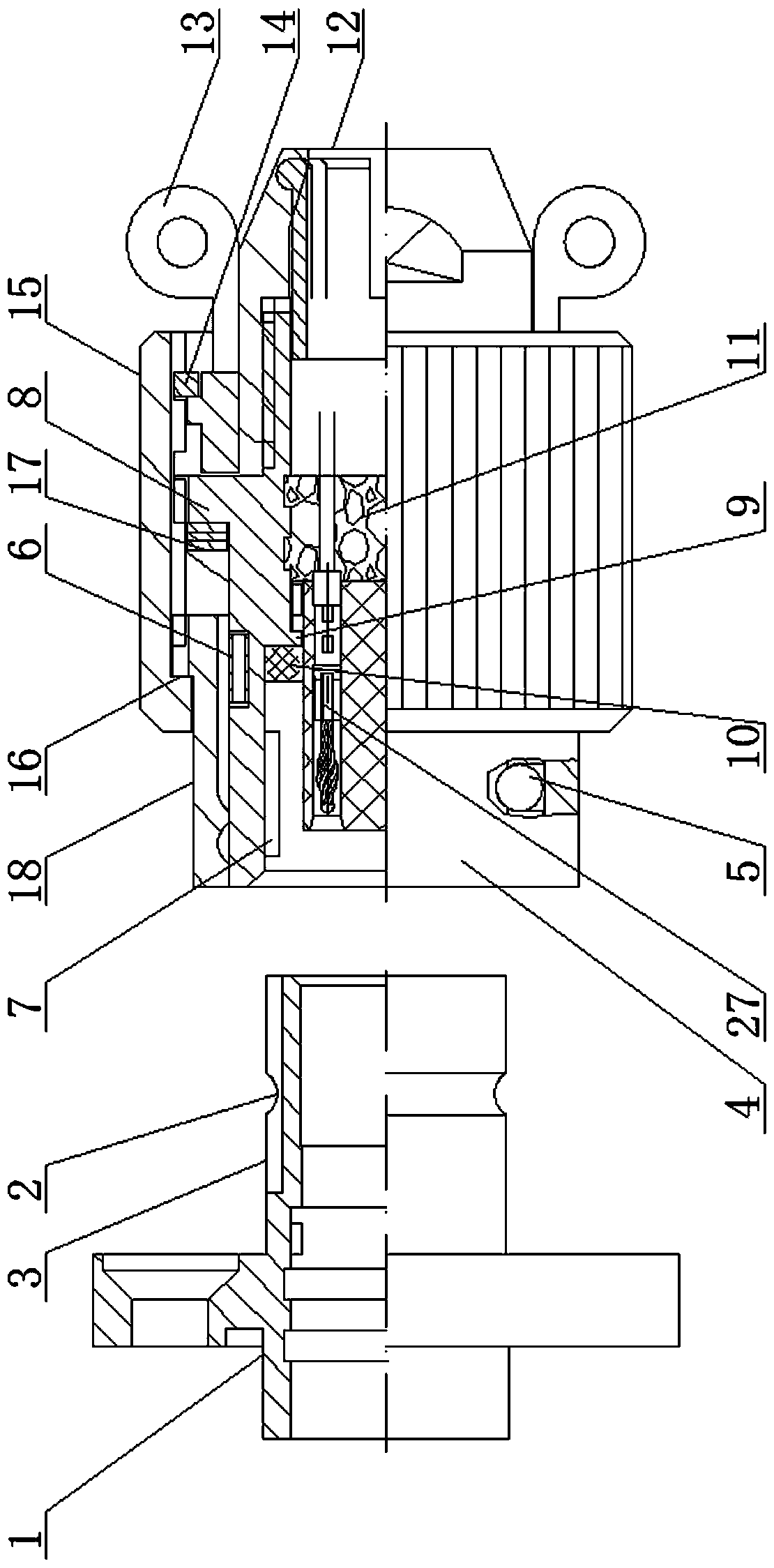
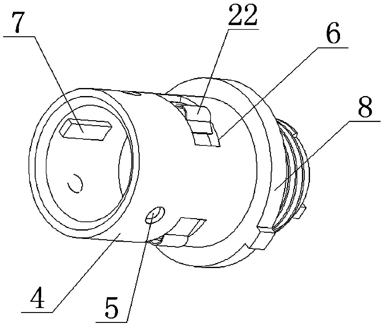
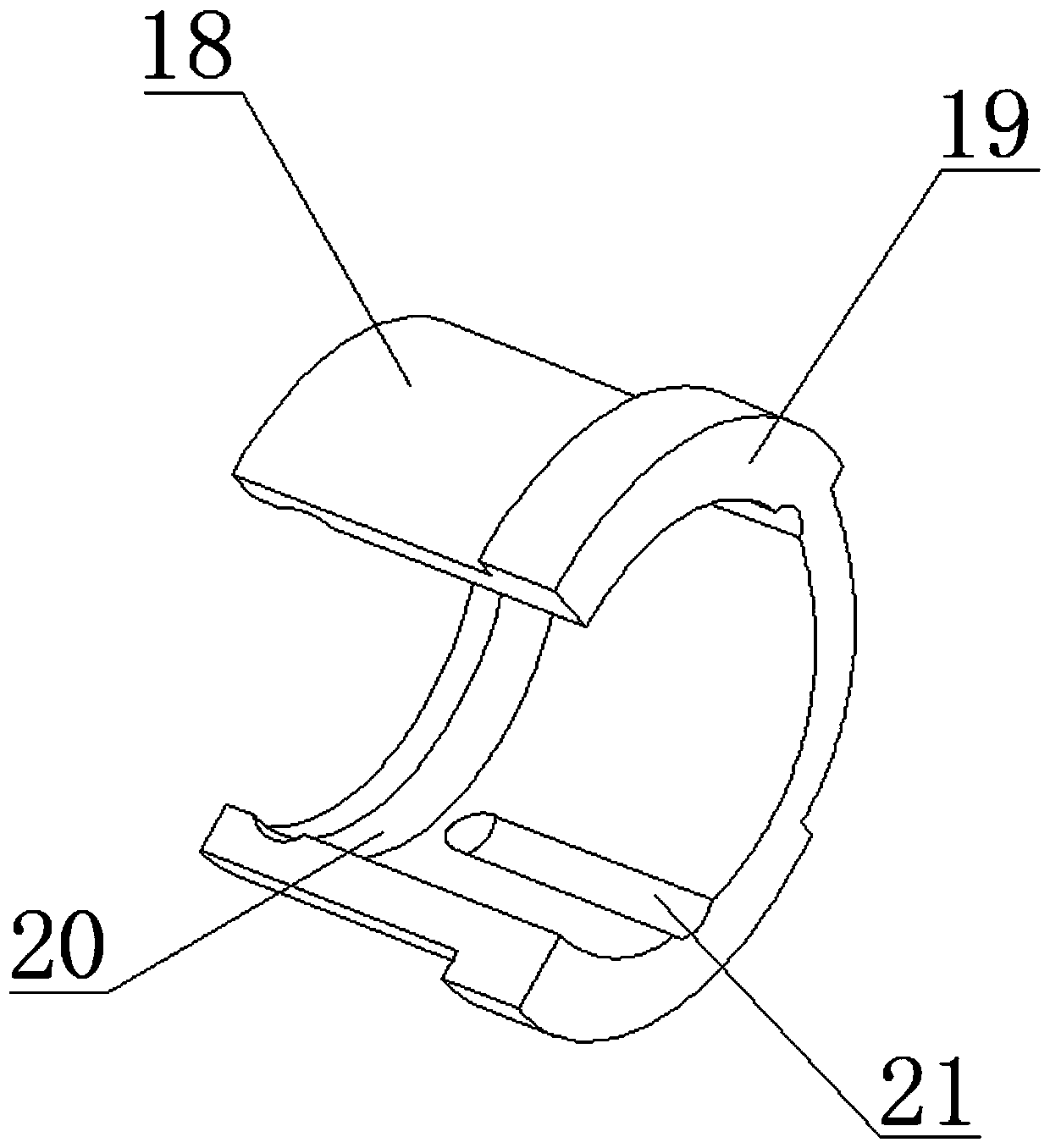
[0023] Figure 1-4 As shown: a spring-type self-locking anti-loosening electrical connector includes a plug and a socket. One end of the seat shell 1 of the socket is inserted into one end of the head shell 4, and a locking ring is provided on the outer circumference of one end of the seat shell 1. The arc-shaped ring groove 2, the outer circumferential wall of the head shell 4 of the plug is provided with more than two steel balls 5 evenly distributed in the radial limit movement, the other end of the head shell is connected to the tail attachment 12, and the flange in the middle of the head shell 8. A nut 15 is connected to the outer circumference guide sleeve, and one end of the nut 15 is provided with an inner step 16, and a locking ring 18 is radially spaced and sleeved between the outer circumference of one end of the head shell and the nut, and the locking ring 18 is provided w...


PUM


Abstract

The invention relates to a jump ring type self-locking anti-loose connector. The connector includes a plug and a socket, wherein a nut is arranged on the outer circumference of a flange of the middleportion of a head shell, one end of the nut is provided with an inner step, a locking ring is sleeved between the outer circumference of one end of the head shell and the nut, the locking ring is provided with a ring of pull-out bosses, an inner end surface of the locking ring and the head shell abut against a corrugated spring, the other end of the nut is connected with a pull ring between the nut and a tail accessory through a retaining ring for limiting, an inner wall of an outer side of the locking ring is provided with a ring of pull-off arc-shaped annular grooves, an inner wall of an inner side of the locking ring is provided with two circumferentially distributed arc-shaped through grooves, an outer circumference of one end of the head shell is provided with two or more circumferentially arranged jump ring grooves, jump rings are arranged in the jump ring grooves, and the jump rings are in one-to-one correspondence with steel balls and are not on the same axis of an outer wall of the head shell. The connector is advantaged in that the steel balls are utilized for locking connection in cooperation with circumferential rotation of limit steel balls for secondary locking, the structure is simple, locking and unlocking are convenient, self-locking loosening is prevented, and connection is stable and reliable.

Description

technical field [0001] The invention relates to a connector, in particular to a spring-type self-locking and anti-loosening electrical connector. Background technique [0002] The locking methods of traditional electrical connectors can generally be divided into the following types: 1. Bayonet type. The locking force after mating is maintained by the pressure generated by the spring. The disadvantage is that it cannot be rigidly locked. It is easy to disengage when the connector is heavy; 2. Thread type, the locking force depends on the friction between the threads, and it is easy to loosen under strong vibration and impact conditions. Some ratchets are added to prevent it, but the structure of the product Complicated, which increases the manufacturing cost; 3. In-line push-pull type-use the expansion and contraction of the steel ball to achieve the locking of the connector, but the operation is complicated. After the insertion is in place, the shell needs to be rotated to r...

Claims


Application Information

Patent Timeline
Patent Type & Authority Applications(China)
IPC IPC(8): H01R13/625H01R13/633H01R24/00
CPCH01R13/625H01R13/6335H01R24/005
Inventor 叶楠殷志根叶鹏徐继华李竹法
Owner CHINA NORTH IND GRP HANGLIAN TECH CO LTD
Why Eureka
Try Eureka