Shoe sole edge-trimming device for slipper processing
A technology for edge trimming and slipper, which is applied in the direction of grinding drive devices, metal processing equipment, grinding/polishing safety devices, etc. It can solve the problems of increased labor intensity and scattered waste, and achieve the effect of reducing the labor intensity of cleaning
- Summary
- Abstract
- Description
- Claims
- Application Information
AI Technical Summary
Problems solved by technology
Method used
Image
Examples
Embodiment 1
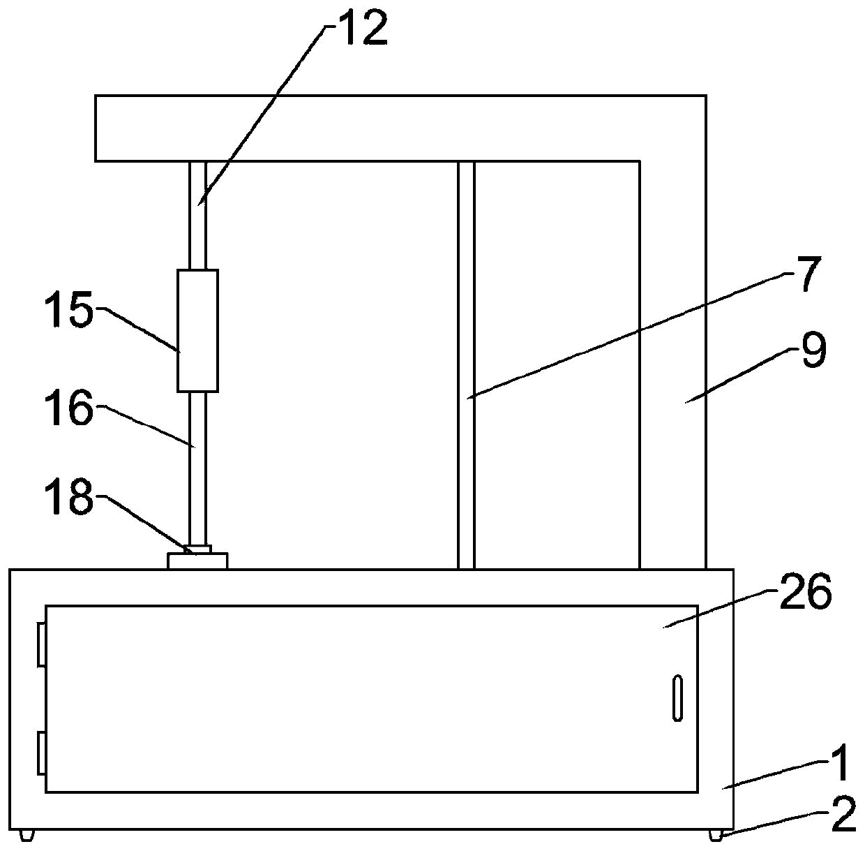
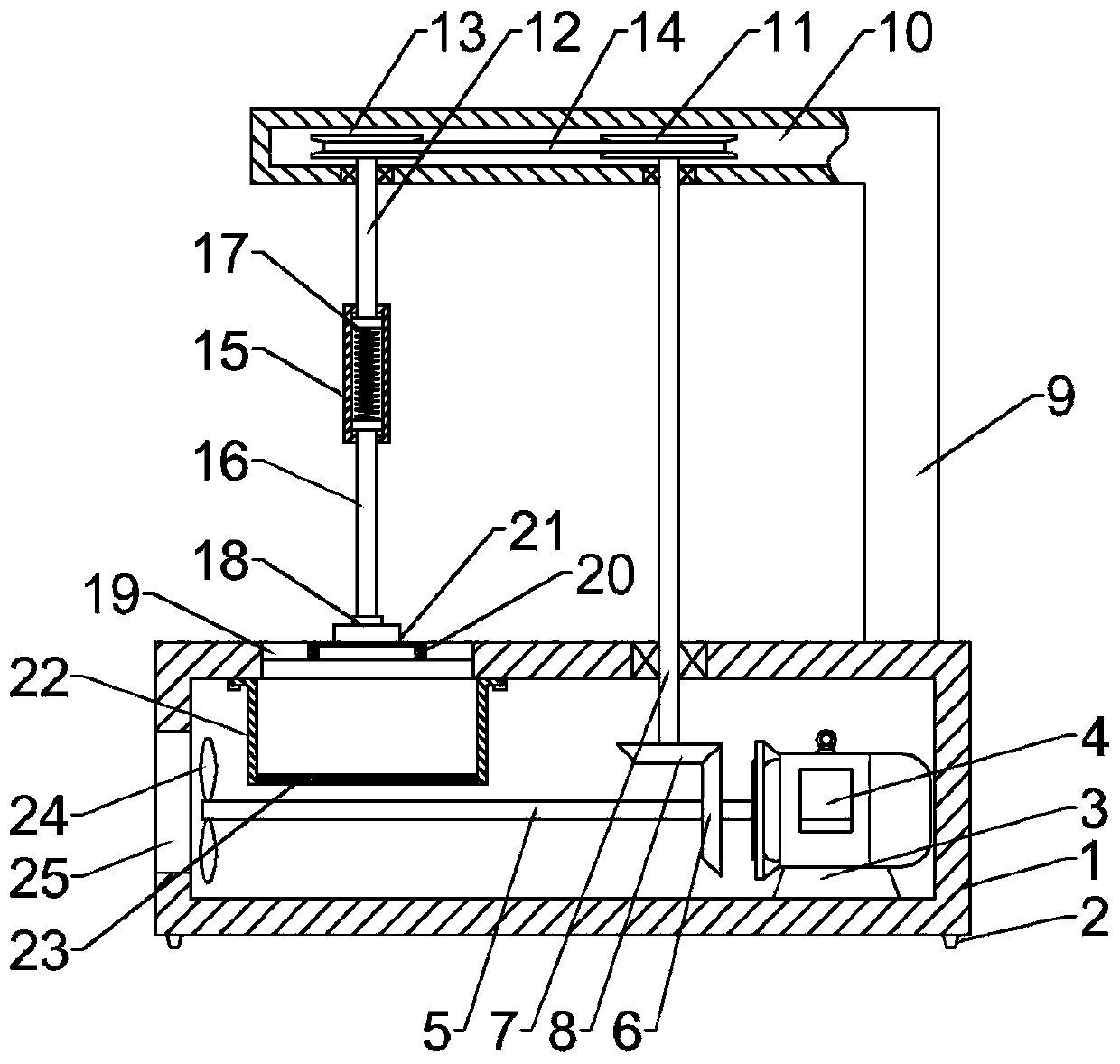
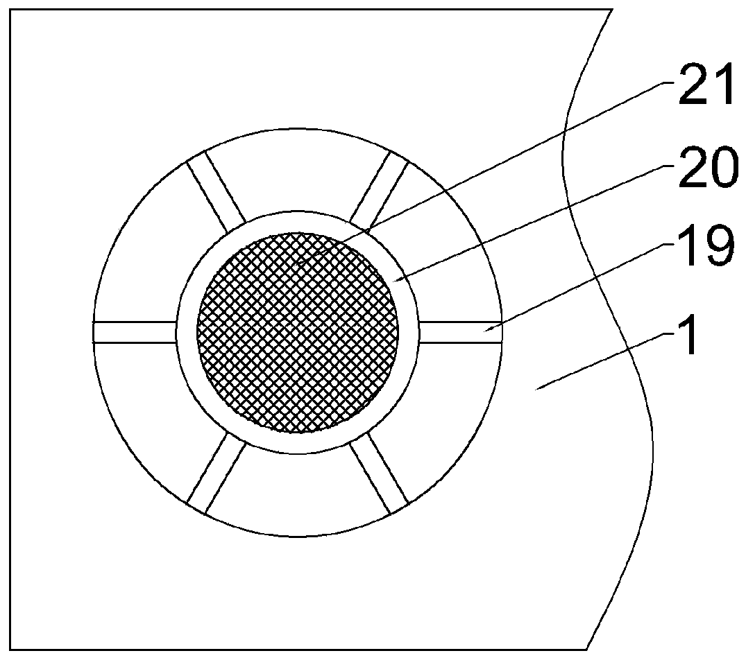
[0021] Example 1: Please refer to Figure 1-4 , a shoe sole trimming device for processing slippers, comprising a lower box body 1, the lower box body 1 is a hollow structure, a motor 4 bracket 3 is fixedly connected to the right side of the inner bottom of the lower box body 1, and a motor 4 bracket 3 is fixedly connected to the top of the motor 4 bracket 3 Motor 4, the output end of the motor 4 is fixedly connected with a horizontal shaft 5, the right side of the horizontal shaft 5 is fixedly connected with a driving bevel gear 6, and the right side of the lower box 1 is connected with a first longitudinal shaft 7 for rotation, the first longitudinal shaft 7. The bottom is fixedly connected with a driven bevel gear 8 meshing with the driving bevel gear 6. It is characterized in that, the upper right side of the lower box 1 is fixedly connected with a support vertical beam 9, and the top of the support vertical beam 9 is provided with a cavity 10. The upper end of the first l...
Embodiment 2
[0031] Example 2: Please refer to Figure 5 , this embodiment is a further improvement of the previous embodiment: the grinding stone 21 is replaced by a flexible planing blade, and the sole can be trimmed more quickly by planing during the rotation process, and the edge trimmed and cut off Strip waste is easier to collect and more convenient to use.
[0032] The working principle of the present invention is: turn on the motor 4 when in use, and drive the horizontal shaft 5 to rotate after the motor 4 is turned on, and the rotation of the horizontal shaft 5 can drive the driving bevel gear 6 to rotate, and the rotation of the driving bevel gear 6 drives the driven bevel gear 8 to rotate. The rotation of the movable bevel gear 8 drives the first longitudinal shaft 7 to rotate, and then drives the driven pulley 13 to rotate through the driving pulley 11 and the transmission belt 14, and the driven pulley 13 can drive the driven pulley 16 through the second longitudinal shaft 12 ...
PUM
 Abstract
Description
Claims
Application Information
 - R&D
- Intellectual Property
- Life Sciences
- Materials
- Tech Scout
- Unparalleled Data Quality
- Higher Quality Content
- 60% Fewer Hallucinations
Browse by: Latest US Patents, China's latest patents, Technical Efficacy Thesaurus, Application Domain, Technology Topic, Popular Technical Reports.
© 2025 PatSnap. All rights reserved.Legal|Privacy policy|Modern Slavery Act Transparency Statement|Sitemap|About US| Contact US: help@patsnap.com


