A kind of stamping equipment with convenient die replacement

A technology for stamping equipment and die replacement, applied in the stamping field, can solve problems such as low efficiency and labor consumption, and achieve the effects of reducing production costs, improving production efficiency, and ensuring stamping effects.

Active Publication Date: 2021-03-05
滁州益佳模具设备制造有限公司
View PDF6 Cites 0 Cited by
  • Summary
  • Abstract
  • Description
  • Claims
  • Application Information

AI Technical Summary

Problems solved by technology

[0004] The purpose of the present invention is to solve the problem of labor-intensive and low efficiency in the prior art, and propose a stamping equipment with convenient mold replacement

Method used


Image

  • A kind of stamping equipment with convenient die replacement
  • A kind of stamping equipment with convenient die replacement
  • A kind of stamping equipment with convenient die replacement

Examples


Embodiment 1

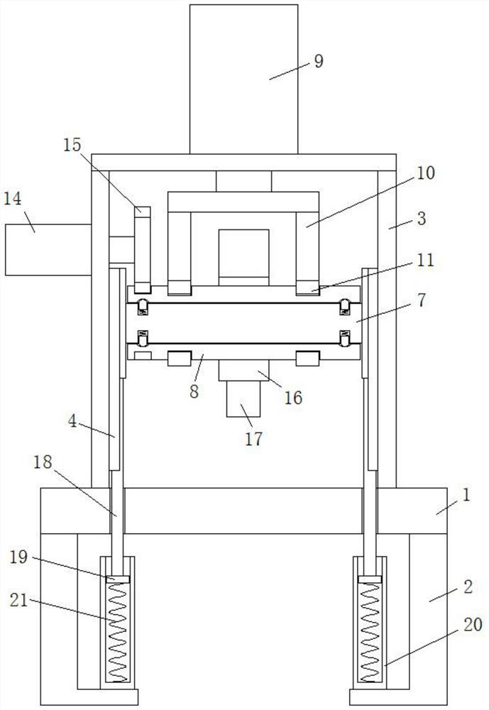
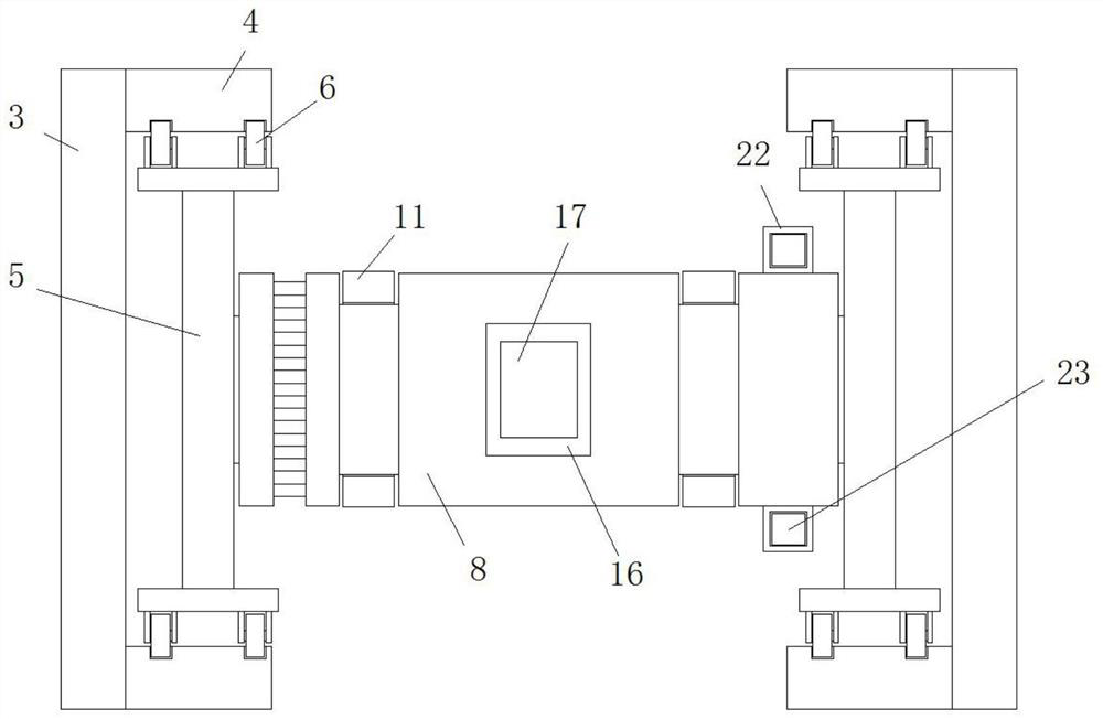
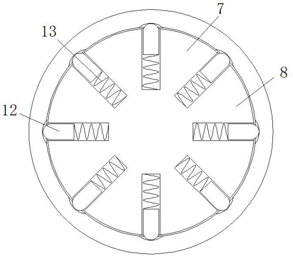
[0023]ReferFigure 1-3One mold replaces the convenient stamping device, including a table 1, and a pin 2 is fixedly connected to the bottom side of the table 1. The top side of the table 1 is provided with a U-shaped plate 3, the U-shaped plate plate 3 is vertical The inner walls of the two sides are fixedly coupled with orbital plates, and the track stands are two and vertical parallel, and the two rail sets are all adjacent to each other, and there is a vertical track slide, and the track is vertically A vertical slide 5 is provided between the plates 4, and the track wheel 6 is provided on both sides of the vertical slide 5, and the track wheel 6 is slidably connected to the vertical track slot, and the center shaft 7 is disposed vertically above the table 1. The two ends of the center shaft 7 are fixed to the vertical slide 5, respectively, and the outer rotating sleeve of the axle body of the center shaft 7 is provided with a drum 8, and an annular groove is opened outside the c...

Embodiment 2

[0026]Such asFigure 1-3As shown, the present embodiment is substantially identical to the first embodiment, preferably, the leg 2 is a L-plate structure, and the bottom end of the bottom barrel 20 is fixed to the horizontal plate of the leg 2.

[0027]In this embodiment, the L-shaped plate structure of the leg 2 facilitates the fixation of the bottom barrel 20.

Embodiment 3

[0029]Such asFigure 1-3As shown, the present embodiment is substantially identical to the first embodiment, preferably, the connecting frame 10 is a U-shaped plate structure, and the connecting ring 11 is two and is located on both sides of the mold base 16.

[0030]In this embodiment, the arrangement of the connecting ring 11 can cause relative rotation of the drum 8 and the center shaft 7 in the vertical direction in the vertical direction, and are provided on both sides, in both sides The cartridge 8 is more stable when moving.


PUM


Abstract

The invention discloses a stamping equipment with convenient mold replacement, which comprises a workbench, feet are fixedly connected to both sides of the bottom of the workbench, a U-shaped support plate is arranged on the top side of the workbench, and the U-shaped support plate The inner walls on both sides of the vertical side are respectively fixedly connected with track vertical plates, and there are two track vertical plates respectively arranged vertically and parallelly, and the sides of the two track vertical plates that are close to each other are provided with vertical track chute respectively, and Vertical slide plates are arranged between the track vertical plates, and track wheels are arranged on both sides of the vertical slide plates, and the track wheels are slidably connected in the vertical track chute respectively. shaft, the two ends of the central shaft are respectively fixedly connected with the vertical slide plate, and the outer side of the shaft body of the central shaft is sleeved with a drum. The invention reduces the production cost, improves the production efficiency, ensures the stamping effect, and satisfies the use requirements of people in production and life.

Description

Technical field[0001]The present invention relates to the field of stamping techniques, and more particularly to a mold replacement of a stamping device.Background technique[0002]Stamping is an external force to the plate, strip, pipe, and profiles such as press press and mold, resulting in plastic deformation or separation, thereby obtaining a molding process of workpiece (stamping parts) required for shape and size.[0003]The process of stamping is often not a stamping, but the multi-stage stamping, the advantage of multi-stage stamping is that more precise and better in the process of step-by-step stamping, and now, now the workshop, in progress During the multi-rush, the plurality of cylinders or hydraulic cylinders are often moved by moving a single mold, while the cylinders are high, and thereby enhance the production cost of the entire stamping member, while using a single cylinder to drive different When the mold is stepped by step, it is necessary to frequently replace the m...

Claims


Application Information

Patent Timeline
Patent Type & Authority Patents(China)
IPC IPC(8): B30B1/38B30B15/02
CPCB30B1/38B30B15/026B30B15/028
Inventor 尹伟张友付郑成建王晓佳谭家杰林波
Owner 滁州益佳模具设备制造有限公司
Why Eureka
Try Eureka