Method and device for detecting offset of code spraying position

The technology of a detection device and detection method, which is applied in the direction of measuring device, printing device, optical device, etc., can solve the problems such as poor correction effect of the position of the inkjet code, and achieve the effect of convenient adjustment of the position of the nozzle and reduction of errors

Active Publication Date: 2019-07-12
HUAIAN COLLEGE OF INFORMATION TECH
View PDF8 Cites 2 Cited by
  • Summary
  • Abstract
  • Description
  • Claims
  • Application Information

AI Technical Summary

Problems solved by technology

[0004] Based on this, it is necessary to provide a more effective method and device for detecting the offset of the inkjet inkjet position for the problem of poor correction of the inkjet inkjet position of the traditional inkjet printer

Method used


Image

  • Method and device for detecting offset of code spraying position
  • Method and device for detecting offset of code spraying position
  • Method and device for detecting offset of code spraying position

Examples


Embodiment Construction

[0040] In order to facilitate the understanding of the present invention, the present invention will be described more fully below with reference to the associated drawings. Preferred embodiments of the invention are shown in the accompanying drawings. However, the present invention can be embodied in many different forms and is not limited to the embodiments described herein. On the contrary, the purpose of providing these embodiments is to make the disclosure of the present invention more thorough and comprehensive.

[0041] It should be noted that when an element is referred to as being “fixed” to another element, it can be directly on the other element or there can also be an intervening element. When an element is referred to as being "connected to" another element, it can be directly connected to the other element or intervening elements may also be present. The terms "inner", "outer", "left", "right" and similar expressions are used herein for the purpose of descripti...


PUM


Abstract

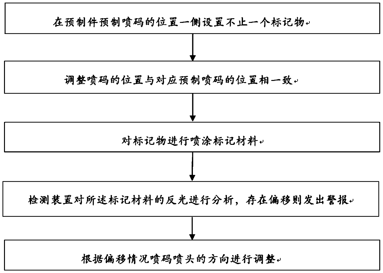
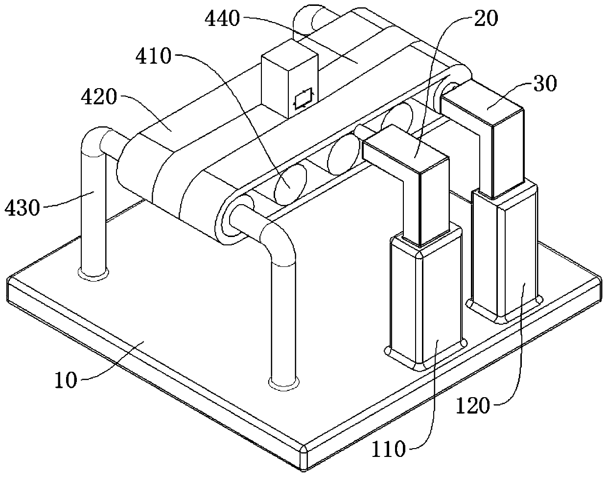
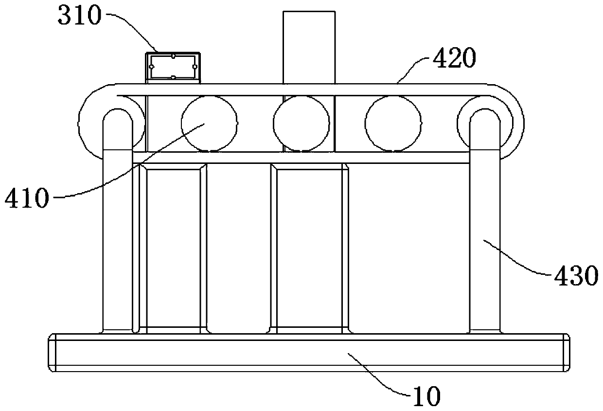
The invention relates to a method and a device for detecting offset of a code spraying position. The method for detecting the offset of the code spraying position comprises the following steps that more than one marker are arranged on one side of a prefabricated code spraying position of a prefabricated part; the code spraying position is adjusted to be consistent with the corresponding prefabricated code spraying position; a marking material is sprayed to the markers; a detection device analyzes the reflection of the marks, and an alarm is given out if the offset exists; and according to theoffset condition, the spraying direction of spraying heads is adjusted. The method has the beneficial effects that the markers on one side of the code spraying position of the prefabricated part havea photosensitive function, and a detection part of the detection device is used for detecting the photosensitive markers; because the markers are of circular truncated cones or conical bulges, the detection part can identify the offset direction according to the color change of photosensitive parts on the bulges, and further fine-tune the position of the spraying heads; and because the detection is carried out according to the change of the photosensitive brightness, the arrangement of bulge structure makes the difference of the photosensitive brightness more obvious and the method is more suitable for staff to identify.

Description

technical field [0001] The invention relates to the technical field of coding detection, in particular to a detection method and device for coding position deviation. Background technique [0002] "Coding" is a verb rather than a noun. It specifically refers to the process of printing information codes by inkjet printers, such as printing production dates, barcodes, QR codes, and serial codes on product packaging, all of which can be called inkjet codes. . Coding is very common now, which is equivalent to the "walking label" of the product, representing the unique characteristics of the product. [0003] Coding can be done on a flat surface, similar to paper, printing bags, etc., and also on curved surfaces, similar to the production date of beverage cans. The quality of the traditional inkjet printer's coding effect is related to many factors. , similar to the temperature and humidity of the environment, the quality of inkjet, the drying speed of ink, etc.; Among them, fo...

Claims


Application Information

Patent Timeline
Patent Type & Authority Applications(China)
IPC IPC(8): B41J29/46G01B11/00
CPCB41J29/46G01B11/00
Inventor 陈玉华刘晓艳钱玲玲徐明辉朱雅恬娄龙全陈啸蒋蕴
Owner HUAIAN COLLEGE OF INFORMATION TECH
Why Eureka
Try Eureka