Control structure of fire-fighting extinguisher valve

A technology of valve control and fire extinguisher, applied in the direction of valve shell structure, lift valve, valve details, etc., to achieve the effect of ensuring sealing performance, reducing pressing resistance, and labor-saving sealing structure

Active Publication Date: 2019-07-12
ZONGDA ELECTRIC CO LTD
View PDF8 Cites 2 Cited by
  • Summary
  • Abstract
  • Description
  • Claims
  • Application Information

AI Technical Summary

Problems solved by technology

[0007] Aiming at the deficiencies in the use of the existing fire extinguisher valve structure proposed in the background technology, the present invention provides a fire extinguisher valve control structure, which has the advantages of labor-saving operation, convenient production and low safety hazards, and solves the above-mentioned background technology. questions raised in

Method used


Image

  • Control structure of fire-fighting extinguisher valve
  • Control structure of fire-fighting extinguisher valve
  • Control structure of fire-fighting extinguisher valve

Examples


Embodiment Construction

[0019] The following will clearly and completely describe the technical solutions in the embodiments of the present invention with reference to the accompanying drawings in the embodiments of the present invention. Obviously, the described embodiments are only some, not all, embodiments of the present invention. Based on the embodiments of the present invention, all other embodiments obtained by persons of ordinary skill in the art without making creative efforts belong to the protection scope of the present invention.

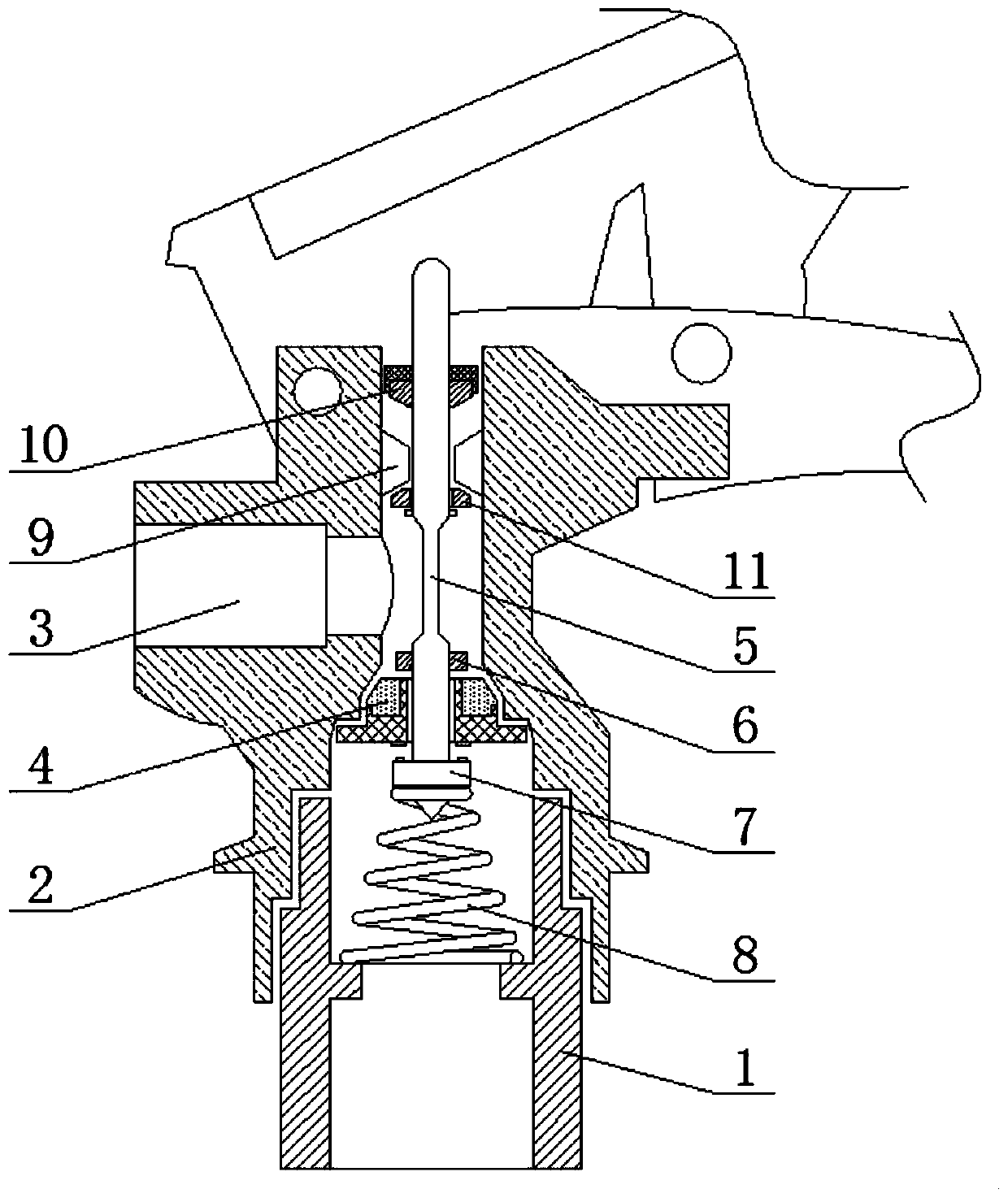
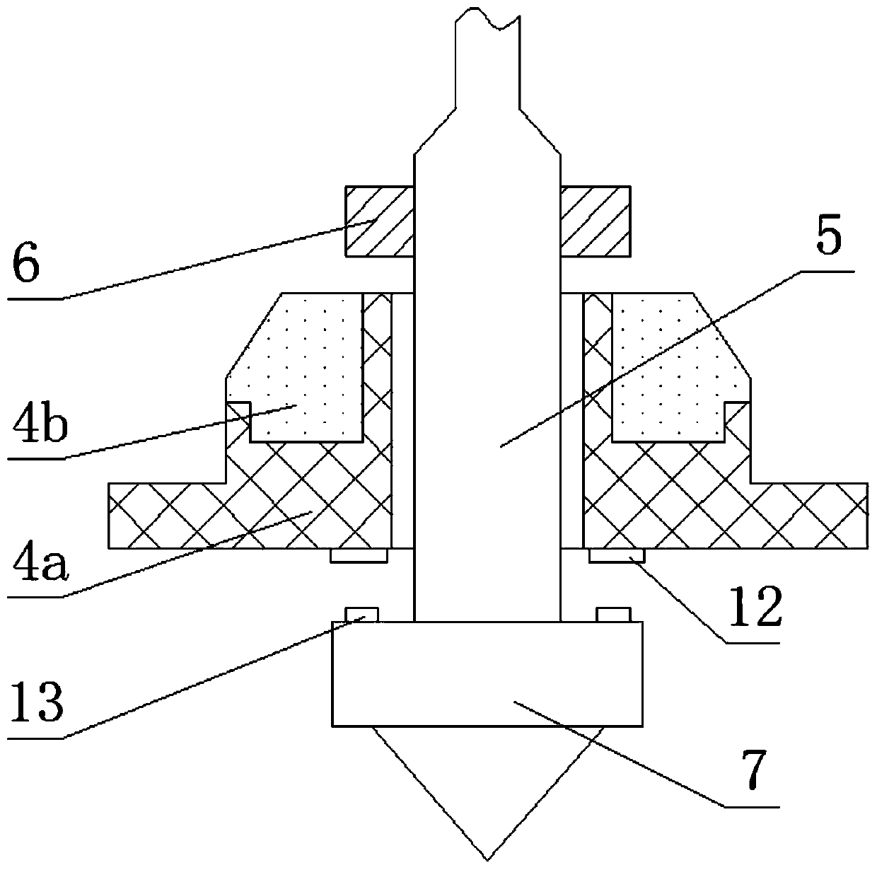
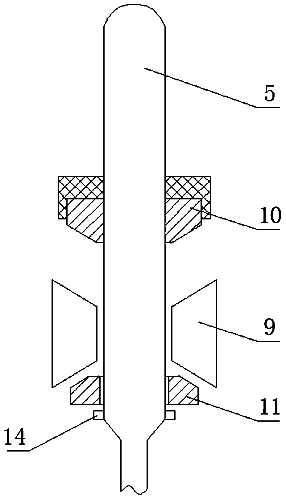
[0020] see Figure 1-3 , a fire extinguisher valve control structure, comprising an upright pipe 1, a valve sleeve 2 threadedly connected to the top of the upright pipe 1 outside, the top of the valve sleeve 2 inner cavity is provided with a horizontal air outlet chamber 3 and a longitudinal sealing chamber, in the air outlet chamber 3 A valve core 4 is provided on the lower side of the inner cavity of the valve sleeve 2 where the size of the cross-section cha...


PUM


Abstract

The invention relates to the technical field of fire-fighting equipment, and discloses a control structure of a fire-fighting extinguisher valve. The control structure comprises a valve sleeve, a valve element and a valve rod, wherein the valve rod is movably sleeved with the valve element, an upper pressing plate and a lower pressing plate are fixedly arranged at the positions, located on the upper side and the lower side of the valve element, of the outer part of the valve rod respectively, the upper pressing plate is used for driving the valve element to move downwards, the lower pressing plate is used for driving the valve element to move upwards, a rubber ring I is fixedly connected to the position, located on the periphery of the valve rod, of the bottom end of the valve element, anda rubber ring II which is arranged corresponding to the rubber ring I is arranged at the top end of the lower pressing plate. According to the control structure, the valve rod is movably sleeved withthe valve element, and the upper pressing plate and the lower pressing plate which are positioned on the upper side and the lower side of the valve element respectively are used for controlling the valve rod to operate the valve element to move up and down, so that the upper side air pressure and the lower side air pressure of the valve element are balanced through separation of the lower pressing plate and the valve element, while the sealing performance is guaranteed, the pressing resistance of a pressing handle due to the inner and outer pressure difference of a bottle is greatly reduced,then, a sealing structure of the valve element is opened by manually pressing the valve rod, and then the effect of being more labor-saving is achieved.

Description

technical field [0001] The invention relates to the technical field of fire fighting equipment, in particular to a valve control structure of a fire extinguisher. Background technique [0002] Fire extinguisher is a kind of portable fire extinguishing tool. According to the fire extinguishing agent filled in the fire extinguisher, it can be divided into foam, dry powder, carbon dioxide, water and other fire extinguishers. The types of fire extinguishers are different, and the valves of the fire extinguisher bottle are different. For gas fire extinguishers such as carbon dioxide, the carbon dioxide gas is compressed and stored in the bottle. When using it, the handle is pressed, and the gas in the bottle is vaporized and released. During daily storage, the sealing of the bottle mouth of the fire extinguisher is high. Traditional When the valve sealing structure is used in a low-temperature environment below -20 degrees Celsius, there will be a problem of fire extinguisher lea...

Claims


Application Information

Patent Timeline
Patent Type & Authority Applications(China)
IPC IPC(8): F16K31/44F16K41/02F16K1/48F16K1/46F16K27/08A62C13/76
CPCA62C13/76F16K1/46F16K1/48F16K27/08F16K31/44F16K41/02
Inventor 不公告发明人
Owner ZONGDA ELECTRIC CO LTD
Why Eureka
Try Eureka