
Simple recovery device of plastic bottle

A recycling device and a technology for plastic bottles, applied in the field of simple recycling devices for plastic bottles, can solve the problems of being unsuitable for small business production, occupying space for mineral water bottles, and slow in compression, and achieve the effects of low production cost, novel design and convenient operation.

Inactive Publication Date: 2018-11-30
唐师正
View PDF6 Cites 2 Cited by
  • Summary
  • Abstract
  • Description
  • Claims
  • Application Information

AI Technical Summary

Problems solved by technology

[0002] Discarded mineral water bottles take up a lot of space when recycling, so plastic bottles need to be compressed and recycled. At present, it is relatively simple to recycle manually, but this compression method is very slow and requires a lot of manpower and labor. At present Special equipment for recycling and compressing plastic bottles has appeared in the equipment, but the production cost of this large-scale equipment is very high, and it is not suitable for the production of small enterprises.

Method used


Image

  • Simple recovery device of plastic bottle
  • Simple recovery device of plastic bottle
  • Simple recovery device of plastic bottle

Examples


Embodiment 1

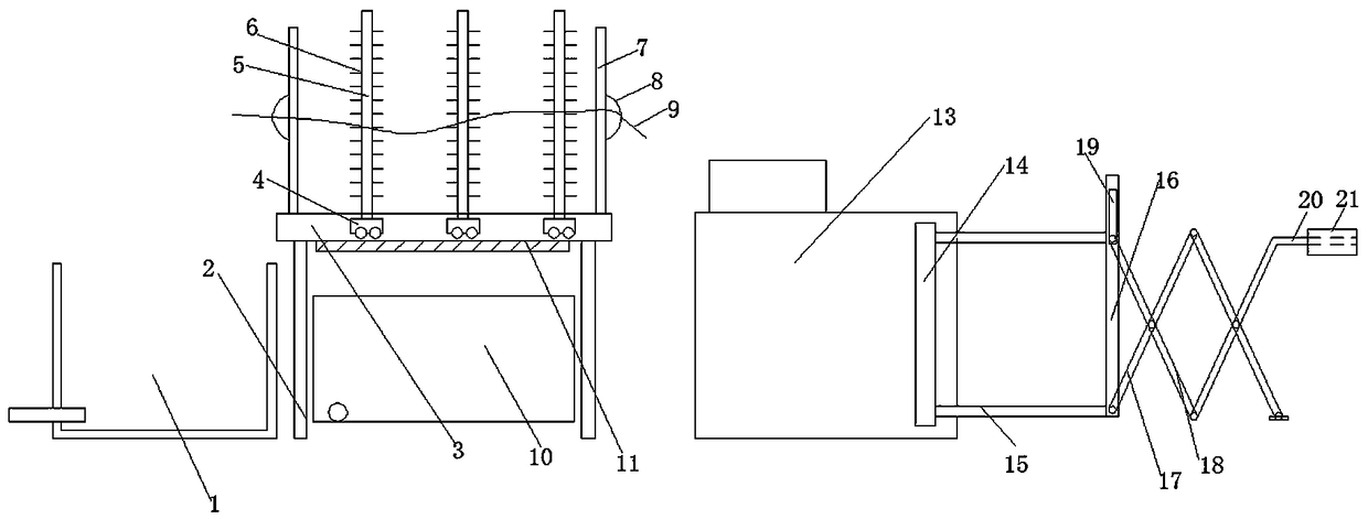
[0016] Such as figure 1 As shown, the present invention is a simple recovery device for plastic bottles, comprising a immersion pool 1 and a squeeze box 13, the lower end of the immersion pool has a water discharge hole, which is beneficial to the outflow of water, and a draining device is also arranged on one side of the immersion pool 1 , the draining device includes a bracket 2, two sliding grooves 3 are arranged in parallel on the bracket 2, and a partition plate 5 driven by a pulley 4 is set between the two sliding grooves 3. The pulley is Shenzhen Baoan The pulleys produced by Yanfeng Architectural Door and Window Fittings Firm in Xin'an District, there are two pulleys under each partition to facilitate the movement of the partition. Baffle plate 7 is also respectively set at the end, that is to say, there are respectively baffle plates on the left and right sides of the draining device, and hanging rings 8 are respectively arranged on the outside of said baffle plate 7,...

Embodiment 2

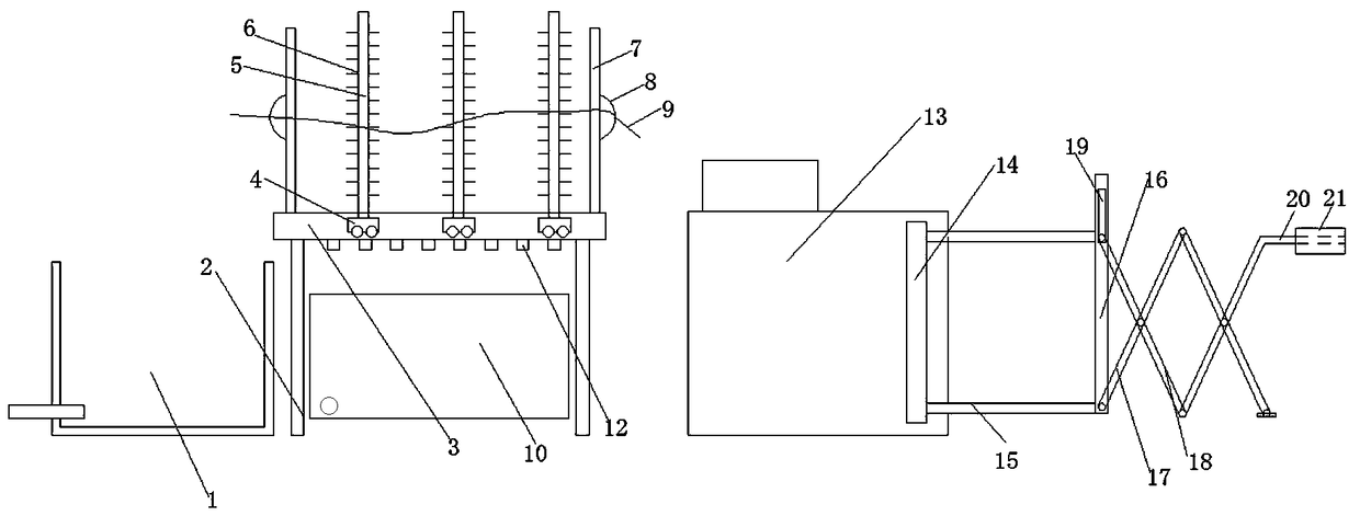
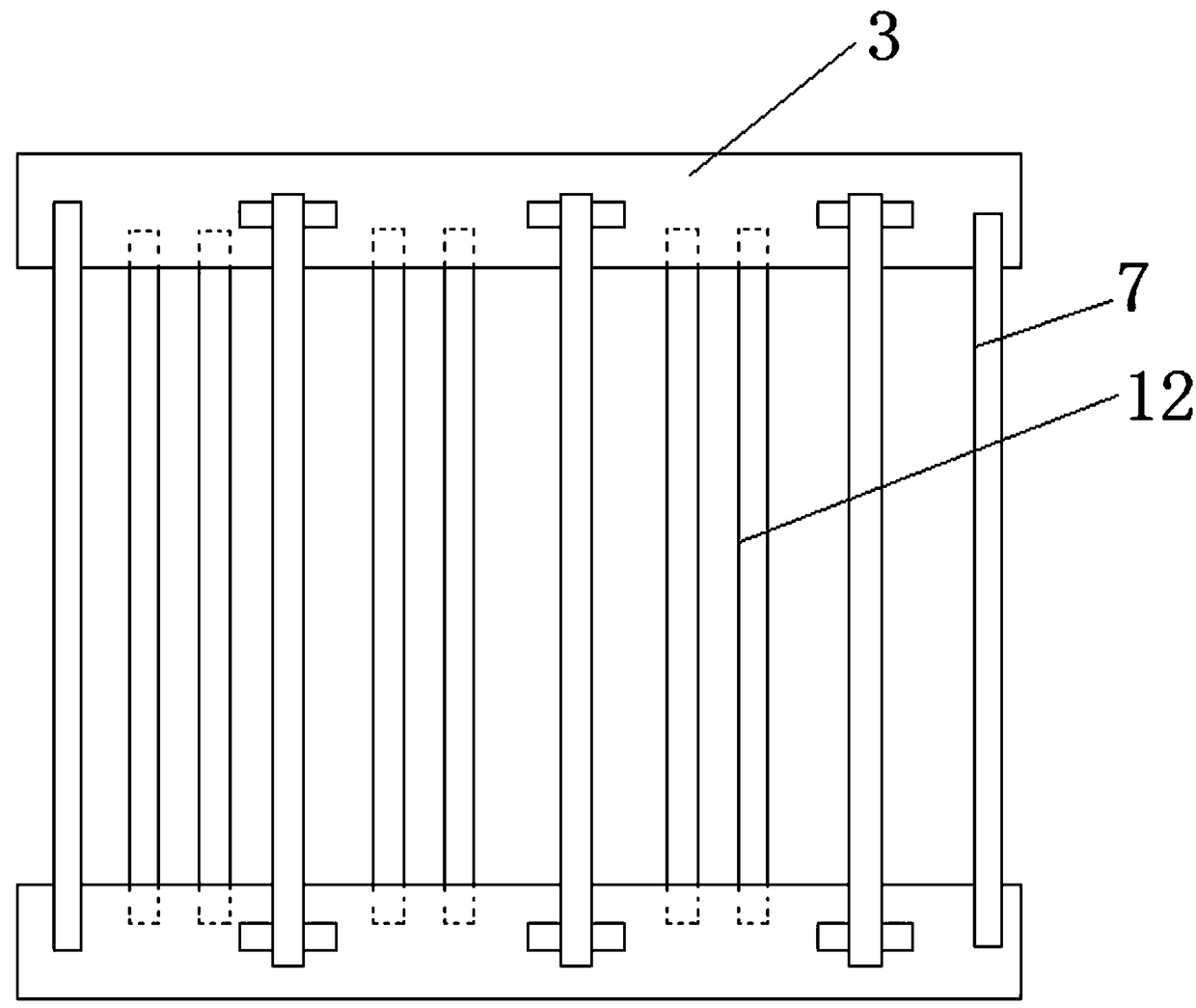
[0019] Such as Figure 2-3 As shown, the present invention is a simple recovery device for plastic bottles, comprising a immersion pool 1 and a squeeze box 13, the lower end of the immersion pool has a water discharge hole, which is beneficial to the outflow of water, and a draining device is also arranged on one side of the immersion pool 1 , the draining device includes a support 2, two sliding grooves 3 are arranged in parallel on the support 2, and a partition plate 5 driven by a pulley 4 is set between the two sliding grooves 3. The pulley is Shenzhen Baoan The pulleys produced by Yanfeng Architectural Door and Window Fittings Firm in Xin'an District, there are two pulleys under each partition to facilitate the movement of the partition. Baffle plate 7 is also respectively set at the end, that is to say, there are respectively baffle plates on the left and right sides of the draining device, and hanging rings 8 are respectively arranged on the outside of said baffle plate...


PUM


Abstract

The invention relates to a simple recovery device of a plastic bottle. The simple recovery device comprises an immersion tank and an extrusion tank. A drainage device is arranged in one side of the immersion tank. The upper part of the extrusion tank is provided with a feeding inlet. One end of the extrusion tank is provided with an extrusion plate. The upper and lower ends of the extrusion plateare respectively provided with sliding columns. A sliding plate connects the two sliding columns. One side of the sliding plate is provided with a sliding slot hole. The sliding plate is respectivelyand movably provided with a first telescopic rod and a second telescopic rod. The first telescopic rod is movably connected to the intersection of the second telescopic rod. One end of the first telescopic rod is arranged on the ground through a base. One end of the second telescopic rod is provided with a push-pull rod. The simple recovery device can effectively complete the cleaning and compression of the plastic bottle, is easy to operate and has a low production cost.

Description

technical field [0001] The invention relates to a recycling device, in particular to a simple recycling device for plastic bottles. Background technique [0002] Discarded mineral water bottles take up a lot of space when recycling, so plastic bottles need to be compressed and recycled. At present, it is relatively simple to recycle manually, but this compression method is very slow and requires a lot of manpower and labor. At present Special equipment for recycling and compressing plastic bottles has appeared in the equipment, but the production cost of this large-scale equipment is very high, and it is not suitable for the production of small enterprises. Contents of the invention [0003] In order to solve the above problems, the present invention provides a simple recycling device for plastic bottles, which is low in cost, easy to operate, and can effectively complete recycling of plastic bottles. [0004] In order to achieve the above object, the present invention is...

Claims


Application Information

Patent Timeline
Patent Type & Authority Applications(China)
IPC IPC(8): B29B17/00
CPCB29B17/0052B29B2017/0015B29B2017/0057Y02W30/62
Inventor 唐师正
Owner 唐师正
Learn More