
Testing device of electromagnet attraction force and motion displacement

A testing device and motion displacement technology, applied in measuring devices, mechanical measuring devices, magnetic properties measurement, etc., can solve the problems of complicated calculation, and achieve the effect of accurate motion displacement and accurate measurement

Active Publication Date: 2019-07-12
HUBEI SANJIANG AEROSPACE HONGFENG CONTROL
View PDF4 Cites 6 Cited by
  • Summary
  • Abstract
  • Description
  • Claims
  • Application Information

AI Technical Summary

Problems solved by technology

[0002] An electromagnet is a device that generates electromagnetism when it is energized. It is composed of a coil and a magnetically conductive material. The electromagnet is magnetic when it is energized, and the magnetism disappears after the power is turned off. Electromagnets are widely used in our daily life. The invention of the invention has also greatly improved the power of the generator; when using it, it is necessary to know the value of the attraction force and displacement of the electromagnet, which is often obtained through calculation, and the calculation is very complicated; it is necessary to design a method for the attraction force and displacement of the electromagnet. The test device is required to be able to measure the displacement while measuring the suction force. At present, there is no such linkage test device

Method used


Image

  • Testing device of electromagnet attraction force and motion displacement
  • Testing device of electromagnet attraction force and motion displacement
  • Testing device of electromagnet attraction force and motion displacement

Examples


Embodiment Construction

[0024] The technical solutions of the present invention will be clearly and completely described below in conjunction with the accompanying drawings of the present invention. Based on the embodiments of the present invention, all other embodiments obtained by persons of ordinary skill in the art without creative efforts fall within the protection scope of the present invention.

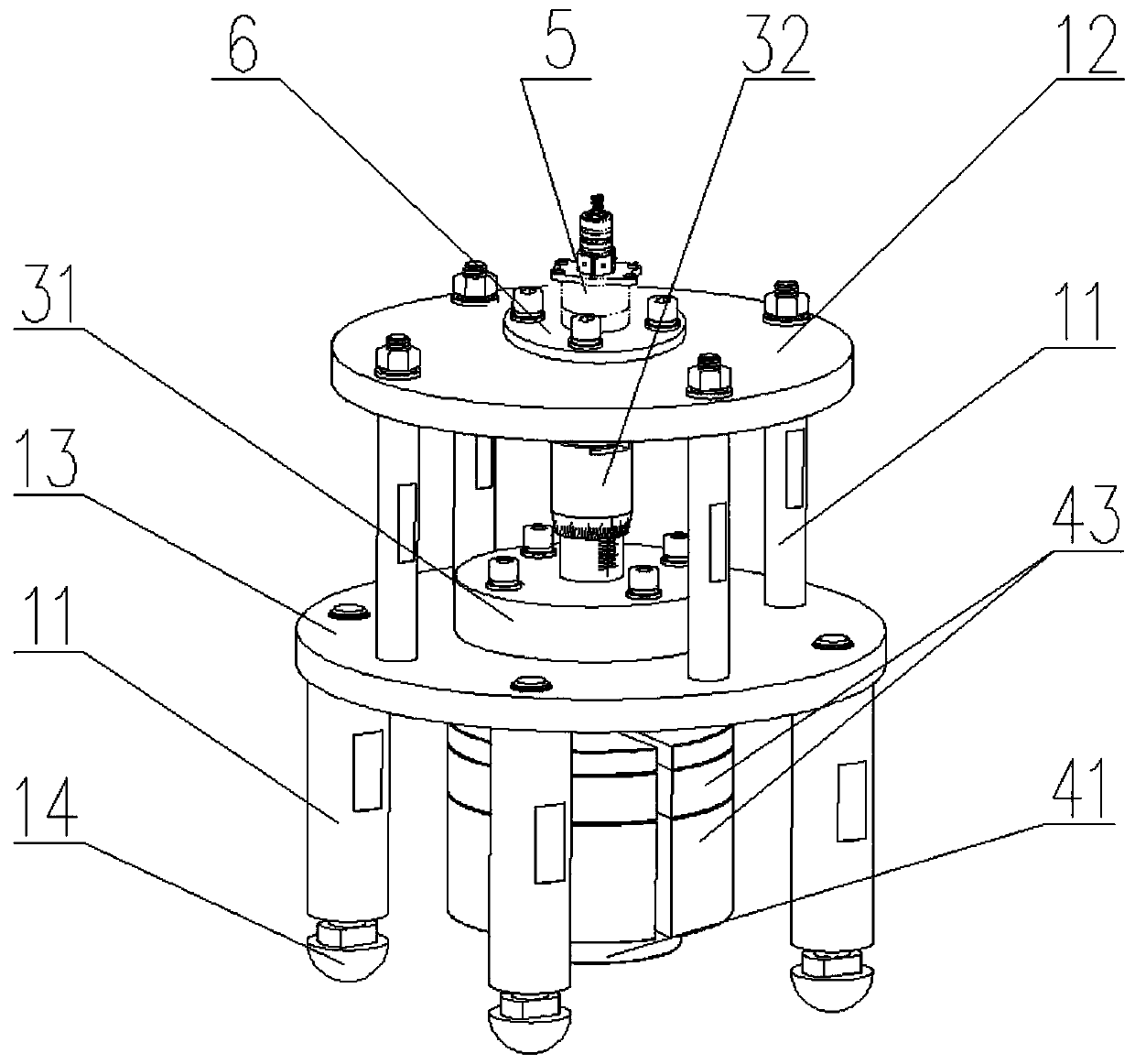
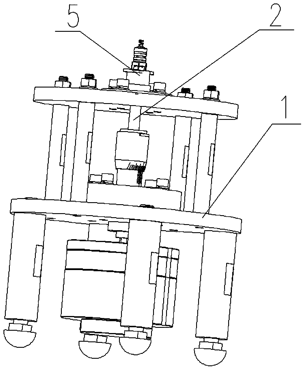
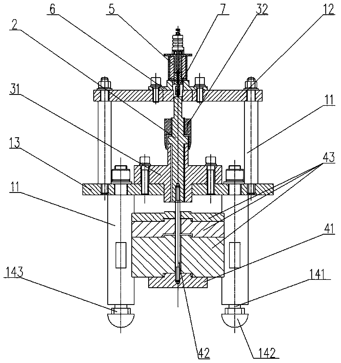
[0025] like Figure 1 to Figure 11 As shown, a test device for electromagnet attraction and motion displacement includes a base frame 1, a motion spindle 2, a displacement measurement assembly, and a gravity assembly. The center of the base frame 1 is provided with a through hole, and one end of the motion spindle 2 is connected to the The armature 51 of the measuring electromagnet 5 is connected, and the other end passes through the base frame 1 and is connected with the gravity component. The moving main shaft 2 can move axially along the measured electromagnet 5. The displacement measuring componen...


PUM


Abstract

The invention discloses a testing device of electromagnet attraction force and motion displacement. The testing device comprises a foundation frame, a motive spindle, a displacement measuring assemblyand a gravity assembly; a through hole is formed in the center of the foundation frame, one end of the motive spindle is connected with an armature of a tested electromagnet, and the other end of themotive spindle penetrates through the foundation frame to be connected with the gravity assembly; the motive spindle can axially move along the tested electromagnet; the displacement measuring assembly comprises a fixed shaft sleeve and a movable shaft sleeve; scale lines are arranged on the outer circumferential faces of the fixed shaft sleeve and the movable shaft sleeve correspondingly; the fixed shaft sleeve movably sleeves the outer side of the motive spindle and is fixedly connected with the foundation frame; the movable shaft sleeve sleeves the motive spindle, and the bottom of the movable shaft sleeve is arranged on the outer side of the fixed shaft sleeve; and the tested electromagnet is arranged on the foundation frame. By adopting the testing device, the numerical value of theelectromagnet attraction force can be accurately obtained by increasing and decreasing weights, and meanwhile the magnitude of the motion displacement of the armature under the effect of the electromagnet attraction force can be read out intuitively.

Description

technical field [0001] The invention belongs to the field of electromagnet testing, in particular to an electromagnet attraction and displacement testing device. Background technique [0002] An electromagnet is a device that generates electromagnetism when it is energized. It is composed of a coil and a magnetically conductive material. The electromagnet is magnetic when it is energized, and the magnetism disappears after the power is turned off. Electromagnets are widely used in our daily life. Because of its The invention of the invention has also greatly improved the power of the generator; when using it, it is necessary to know the value of the attraction force and displacement of the electromagnet, which is often obtained through calculation, and the calculation is very complicated; it is necessary to design a method for the attraction force and displacement of the electromagnet. The test device is required to be able to measure the displacement while measuring the suc...

Claims


Application Information

Patent Timeline
IPC IPC(8): G01R33/12G01B5/02G01L1/08
CPCG01B5/02G01L1/08G01R33/1253
Inventor 钟小艳
Owner HUBEI SANJIANG AEROSPACE HONGFENG CONTROL
Learn More