Monitoring camera

A technology for monitoring cameras and controllers, applied in mechanical equipment, image communication, machines/engines, etc., can solve the problems of fog, affecting the clarity of the monitoring head, and unusable monitors, saving energy, maintaining clear monitoring, simple structure

Active Publication Date: 2019-07-12
新疆九安智慧科技股份有限公司
View PDF8 Cites 3 Cited by
  • Summary
  • Abstract
  • Description
  • Claims
  • Application Information

AI Technical Summary

Problems solved by technology

[0002] The existing monitoring camera is electrically connected to the external power supply, and when the mains power is disconnected or fails, the monitor will not be able to be used. Secondly, in winter, when the temperature difference between the inside of the monitoring protective cover and the outside is large, fog will be generated, affecting the monitoring head. clarity, for this reason, it is necessary to further improve the existing surveillance cameras, so as to improve the use value of surveillance

Method used


Image

  • Monitoring camera
  • Monitoring camera
  • Monitoring camera

Examples


Embodiment Construction

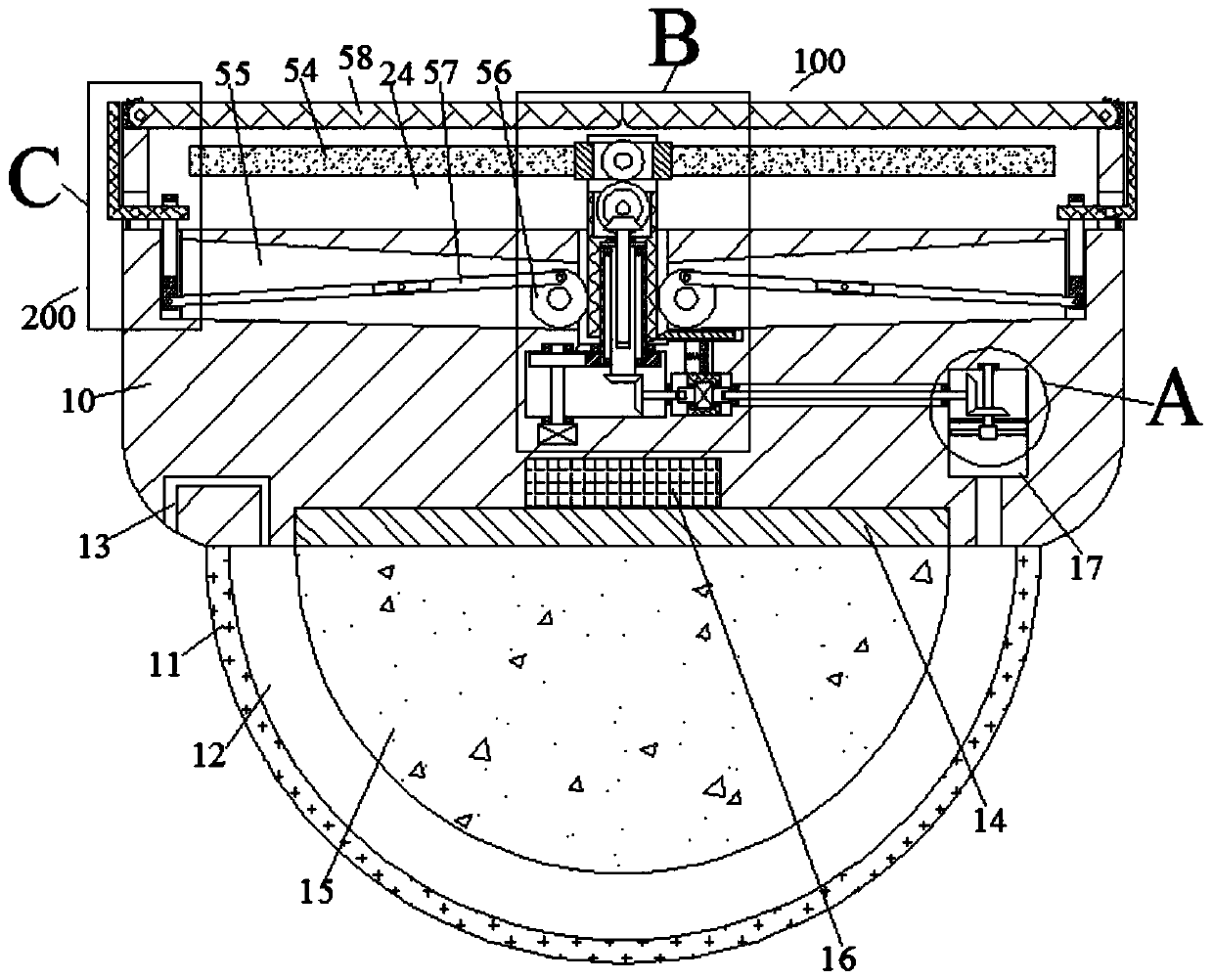
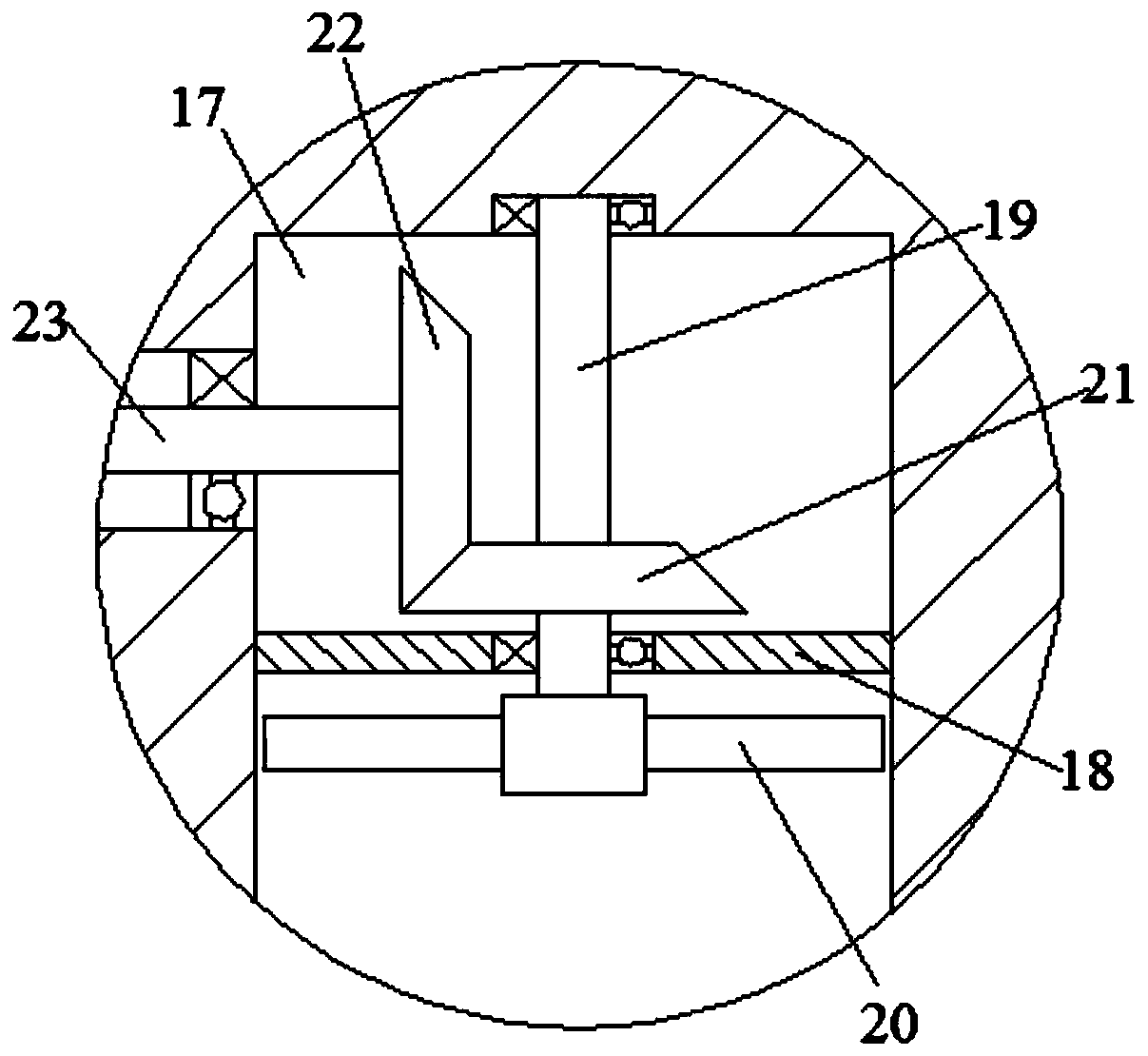
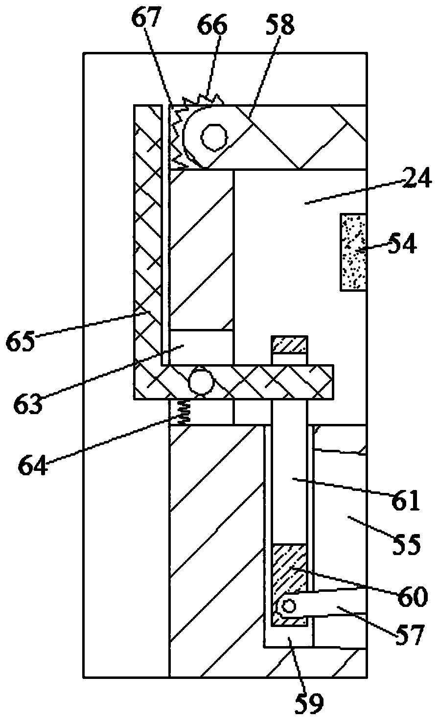
[0015] Combine below Figure 1-6 The present invention is described in detail, and for convenience of description, the orientations mentioned below are now stipulated as follows: figure 1 The up, down, front, back, left, and right directions of the projection relationship are the same.

[0016] refer to Figure 1-6 , a monitoring camera according to an embodiment of the present invention, comprising a main body 10, a shield 11 is fixed on the lower end surface of the main body 10, a cavity 12 is arranged inside the shield 11, and the left side of the cavity 12 is connected to the An air duct 13 is connected to the outside world, a controller 14 is fixed in the upper end wall of the cavity 12, a monitoring head 15 is fixed at the lower end of the controller 14, and a battery 16 is electrically connected to the upper end of the controller 14 , the upper side of the storage battery 16 is provided with an electric energy device 100, the electric energy device 100 is electrically...


PUM


Abstract

The invention discloses a monitoring camera. The monitoring camera comprises a body, a protective cover is fixedly arranged on the lower end surface of the main body; a cavity is formed in the protective cover; a controller is fixedly arranged in the upper end wall of the cavity; a monitoring head is fixedly arranged at the lower end of the controller; the upper end of the controller is electrically connected with a storage battery; and an electric energy device is arranged on the upper side of the storage battery and electrically connected with the storage battery. According to the invention,the monitoring camera is simple in structure and convenient to operate, power is supplied to the monitoring head through the solar panel for use, energy is saved, the solar panel is protected, the service life of the solar panel is long, and secondly, the monitoring camera can conduct demisting treatment, so that monitoring is kept clear.

Description

technical field [0001] The invention relates to the technical field of monitoring equipment, in particular to a monitoring camera. Background technique [0002] The existing monitoring camera is electrically connected to the external power supply, and when the mains power is disconnected or fails, the monitor will not be able to be used. Secondly, in winter, when the temperature difference between the inside of the monitoring protective cover and the outside is large, fog will be generated, affecting the monitoring head. For this reason, it is necessary to further improve the existing surveillance cameras, so as to improve the use value of surveillance. Contents of the invention [0003] The object of the present invention is to provide a monitoring camera for overcoming the above-mentioned defects in the prior art. [0004] A monitoring camera according to the present invention includes a main body, a shield is fixed on the lower end of the main body, a cavity is provide...

Claims


Application Information

Patent Timeline
Patent Type & Authority Applications(China)
IPC IPC(8): H04N5/225H02J7/35F04D25/12
CPCH02J7/35F04D25/12H04N23/50
Inventor 程苏娟
Owner 新疆九安智慧科技股份有限公司
Why Eureka
Try Eureka