Device and method for adjusting position of flat panel detector and radiation therapy device

A flat-panel detector and adjustment device technology, which is applied to radiation detection devices, radiotherapy, X-ray/γ-ray/particle irradiation therapy, etc., can solve the problems of poor operation efficiency of flat-panel detectors, and achieve the effect of improving operation efficiency

Active Publication Date: 2021-04-27
TOSHIBA FUEL CELL POWER SYST +1
View PDF7 Cites 0 Cited by
  • Summary
  • Abstract
  • Description
  • Claims
  • Application Information

AI Technical Summary

Problems solved by technology

However, it is necessary to alternately repeat the imaging of X-ray images and the movement of the flat panel detector until the flat panel detector reaches an appropriate position, and there is a problem that the operation efficiency of the position adjustment of the flat panel detector is poor.

Method used


Image

  • Device and method for adjusting position of flat panel detector and radiation therapy device
  • Device and method for adjusting position of flat panel detector and radiation therapy device
  • Device and method for adjusting position of flat panel detector and radiation therapy device

Examples


no. 1 Embodiment approach

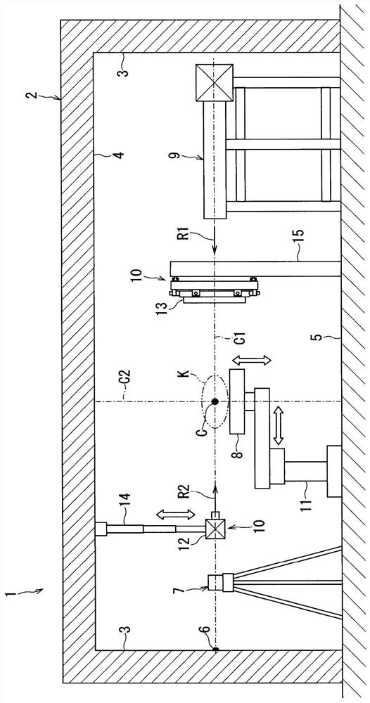
[0024]Hereinafter, the present embodiment will be described based on the drawings. First, useFigure 1 ~ 6The positional adjustment device of the flat plate detector of the first embodiment will be described. Hereinafter,figure 1 andimage 3 The left side of the paper is described as the front side (front side) of the flat panel detector and the position adjustment device.

[0025]figure 1 Reference numeral 1 is a radiation therapy device. The radiation treatment device 1 is disposed in the treatment chamber 2. The radiation treatment device 1 is used to illuminate the treatment of the treatment of the treatment of the treatment of the treatment as a tumor or the like produced by the patient K of the subject. Treated radiation uses X-rays, gamma rays, electronics, proton lines, neutron wires, and heavy particle lines. Further, the treatment chamber 2 is a room of the wall 3, the ceiling 4, and the floor 5 that is cut by the concrete made of the radiation.

[0026]In the treatment chamber 2,...

no. 2 Embodiment approach

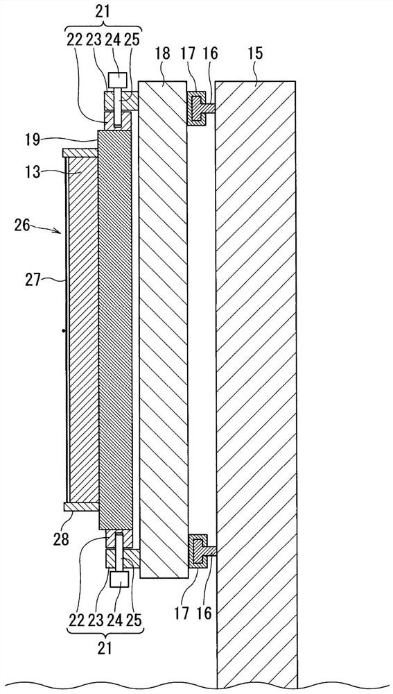
[0085]Next, useFigure 7 withFigure 8 The positional adjustment device 26a of the flat plate detector of the second embodiment will be described. Further, the same components as the constituent portion shown in the above-described embodiments are labeled, and the same reference numerals are marked and the repetitive description is omitted.

[0086]Such asFigure 7 As shown, the position adjustment device 26a of the second embodiment is mounted to the flat plate detector 13. The position adjustment device 26a includes a guide portion 27a that is in contact with the surface of the flat plate detector 13 and a fixing portion 28a fixed to the periphery of the flat plate detector 13.

[0087]The guiding portion 27a includes four metal wires 33, 34, 35, 36 extending from the center of each of the four sides of the four sides of the frame-shaped fixing portion 28a. These metal wires 33, 34, 35, 36 are formed to determine the 2-axis of the two-dimensional coordinate corresponding to the surface of ...

no. 3 Embodiment approach

[0097]Next, useFigure 9 withFigure 10 The positional adjustment device 26b of the flat plate detector of the third embodiment will be described. Further, the same components as those shown in the constituent parts shown in the above-described embodiments are attached, and the repeated description is omitted. Hereinafter,Figure 9 The top left side of the paper surface is described as the front side (front side) of the flat plate detector 13 and the position adjustment device 26b.

[0098]Such asFigure 9 andFigure 10 As shown, the positional adjustment device 26b of the third embodiment is a case-shaped component that is substantially formed in the shape and the back side of the back side in the side cross-section. The position adjustment device 26b cooperates with the flat plate detector 13. The position adjustment device 26b includes a guide portion 27b provided on the front side and a forming box-shaped fixing portion 28b that cooperates with the flat plate detector 13. Further, the p...


PUM


Abstract

The present invention provides a flat panel detector position adjustment technique capable of improving the operational efficiency of the flat panel detector position adjustment. The position adjustment device (26) of the flat panel detector (13) has: a guide part (27), which is arranged on the surface side of the flat panel detector (13), is reflected in the X-ray image and can be measured by the optical device (7); and The fixing part (28) makes the guide part (27) relative to one of the flat panel detector side or the supporting part side of the position adjustment part (21) provided between the flat panel detector (13) and its supporting part (18). And fixed.

Description

Technical field[0001]Embodiments of the present invention relate to the positional adjustment device of a flat plate detector, a position adjustment method of a flat plate detector and a radiation therapeutic device.Background technique[0002]Conventionally, in the radiation therapeutic apparatus, an X-ray tube and a flat panel detector for the photographing of the X-ray image in order to confirm the position of the patient's lesion portion. In such a radiation therapeutic apparatus, the technique of contaminated analog isocenter as a reference to perform a variety of devices is known.[0003]As this technique, there is a Japanese Open Franchise Publication No. 2016-221156 (hereinafter referred to as franchise 1).[0004]In the foregoing technique, photographing anxer of the X-ray image of the body, and is adjusted in the position of the flat plate detector based on the X-ray image. However, it is necessary to alternately repeat the movement of the X-ray image and the movement of the fla...

Claims


Application Information

Patent Timeline
Patent Type & Authority Patents(China)
IPC IPC(8): A61N5/10
CPCA61N5/1048A61N2005/1061A61N2005/1092A61B6/4283A61B6/587A61N5/1049A61B6/585A61B6/4429A61B6/42A61N5/1001A61N5/1077A61B6/4452A61B6/4233G01T1/16A61N5/10
Inventor 小林孝幸伊藤宽昌笠井茂
Owner TOSHIBA FUEL CELL POWER SYST
Why Eureka
Try Eureka