Amphibious robot propelled by undulating fins

An amphibious and robotic technology, applied in the field of robotics, can solve the problems of high control difficulty, low pass rate, and low energy efficiency, and achieve the effect of low control difficulty, high pass rate, and simple structure

Active Publication Date: 2019-07-19
SOUTHWEST PETROLEUM UNIV
View PDF9 Cites 24 Cited by
  • Summary
  • Abstract
  • Description
  • Claims
  • Application Information

AI Technical Summary

Problems solved by technology

[0003] The technical problem to be solved by the present invention is the ubiquitous problems of current amphibious bionic robots: complex structure, difficult control, low motion performance on land and underwater, and low energy efficiency. For amphibious bionic robots, the main technical solutions The problem is the propulsion device of the amphibious bionic robot
For the form of propulsion, the present invention mainly solves...

Method used


Image

  • Amphibious robot propelled by undulating fins
  • Amphibious robot propelled by undulating fins
  • Amphibious robot propelled by undulating fins

Examples


Embodiment 1

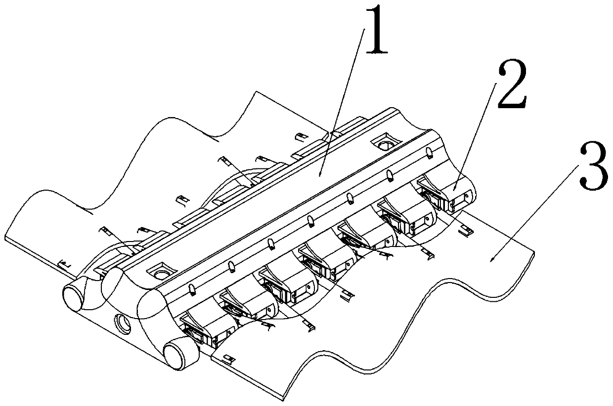
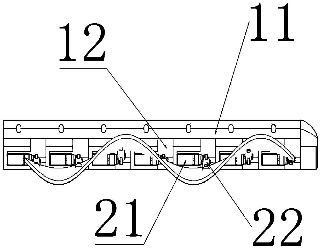
[0025] Such as Figure 1~2 As shown, an amphibious robot propelled by undulating fins in the present invention is characterized in that it includes a body 1, a driving arm unit 2 and an undulating fin 3, and seven driving arm units 2 are respectively arranged on the left and right sides of the body 1, One end of the driving arm unit 2 is connected to the body 1 and the other end is connected to the undulating fin 3, the undulating fin 3 is formed by bending a fan-shaped plane, and the phase difference between the undulating fins 3 connected to two adjacent driving arm units 2 is the largest is 120 degrees, the driving arm unit 2 controls the undulating fin 3 to perform sinusoidal fluctuations, the side end surface of the undulating fin 3 connected to the driving arm unit 2 is the inner end surface, and the side end surface away from the driving arm unit 2 is the outer end surface, The edge line between the inner end face and the outer end face is a sinusoidal line, and the flu...

Embodiment 2

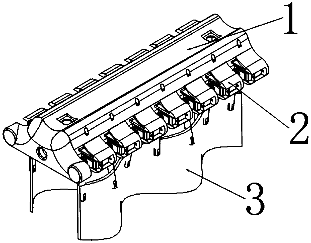
[0029] Such as Figure 3-4As shown, this embodiment is optimized on the basis of Embodiment 1, and there are 7 driving units on one side of the robot proposed in this application document. Under this structure, the phase difference between the drive arm units of the undulating fin is 120 degrees, and the total phase difference is exactly 720 degrees, which can meet this requirement. It needs to be explained that if the phase difference is too large, the load effect on the steering gear of the driving arm will also increase, and it may also make the undulating fin waveform unable to be effectively transmitted. If the phase is too small, the sine wave waveform with a total phase of 720 degrees cannot be provided. This paper After comprehensively analyzing various factors, the invention selects a drive structure consisting of 7 drive arm units on one side. The direction of movement of the robot on flat land is the same as the direction of propagation of the undulating fins (that...

Embodiment 3

[0031] Such as Figure 6 As shown, the application document is optimized on the basis of Embodiments 1 and 2. The electrical circuit includes a lithium battery module, a wireless receiver, a steering gear drive board, a main control board, a depth sensor, a gyroscope, and a servo motor. The lithium battery module supplies power to the main control board and the steering gear drive board. The main control board communicates with the steering gear drive board, depth sensor, and gyroscope through the I2C bus, and communicates with the wireless receiving module through the digital IO port. The main control board communicates through the The steering gear driving board is used to drive the driving arm unit 2 to move. Its electrical circuit such as image 3 As shown (the remote control is not part of the onboard circuit of the robot, so it is not marked in the figure). The lithium battery power module outputs 6V steering gear drive power and 5V main control board power supply. The...


PUM

PropertyMeasurementUnit
Thicknessaaaaaaaaaa
Hardnessaaaaaaaaaa
Shore hardnessaaaaaaaaaa

Abstract

The invention discloses an amphibious robot propelled by undulating fins. The amphibious robot propelled by the undulating fins is characterized by comprising a robot body, driving arm units and the undulating fins; seven driving arm units are arranged on the left and right sides of the robot body; one ends of the driving arm units are connected with the robot body, and the other ends of the driving arm units are connected with the undulating fins; the undulating fins are formed by bending fan-shaped planes; a phase difference between the undulating fins connected with the two adjacent drivingarm units can be freely adjusted according to coordination between the driving arm units, and the maximum phase difference is 120 degrees; the driving arm units control the undulating fins to performsinusoidal undulation; the robot moves on the land through static friction forces between the undulating fins and the ground and moves underwater through the undulating fins and a counter-acting force of pushing water flow; and compared with a traditional amphibious robot, the amphibious robot propelled by the undulating fins has the advantages of simple structure, convenient control, high energyefficiency, low noise and high movement performance.

Description

technical field [0001] The invention relates to a robot, in particular to an amphibious robot propelled by fluctuating fins. Background technique [0002] In terms of undulating fin propulsion technology, there have been many researches and applications of related technologies at home and abroad. For example, the undulating fin bionic underwater thruster and the undulating fin bionic underwater propulsion device developed by the National University of Defense Technology of China and the Shenyang Institute of Automation of the Chinese Academy of Sciences have applied for related patents. There are also many underwater bionic robots that utilize undulating fins to propel. But these robots are underwater robots and cannot move on land. Most of their undulating fins are made of thin and soft rubber, and they have no ability to move on land, and there is no precedent for using undulating fins for propulsion in robots moving on land. Contents of the invention [0003] The tec...

Claims


Application Information

Patent Timeline
IPC IPC(8): B63H1/37B63H21/17
CPCB63H1/37B63H21/17
Inventor 李亚鑫刘雷王宇常永鑫
Owner SOUTHWEST PETROLEUM UNIV
Why Eureka
Try Eureka