Chain traction device for chain conveyor

A chain conveyor and traction device technology, applied in the direction of conveyor, transportation and packaging, can solve problems such as unfavorable use of conveyor, troublesome removal of drive shaft, affecting the life of belt and drive shaft, etc., to improve maintenance efficiency, The effect of avoiding slippage and deviation and increasing production efficiency

Inactive Publication Date: 2019-07-19
安徽华顺智能装备有限公司
View PDF6 Cites 0 Cited by
  • Summary
  • Abstract
  • Description
  • Claims
  • Application Information

AI Technical Summary

Problems solved by technology

[0003] The traction device of the original chain conveyor is driven by the belt and the drive shaft. When the belt moves on the drive shaft, the belt rubs against the drive shaft. The long-term friction makes the surface of the drive shaft smooth, affecting the The life of the belt and drive shaft is shortened. When the belt and drive shaft are damaged and need to be replaced, it is troublesome to disassemble the drive shaft, which is not conducive to the use of the conveyor.

Method used


Image

  • Chain traction device for chain conveyor
  • Chain traction device for chain conveyor
  • Chain traction device for chain conveyor

Examples


Embodiment

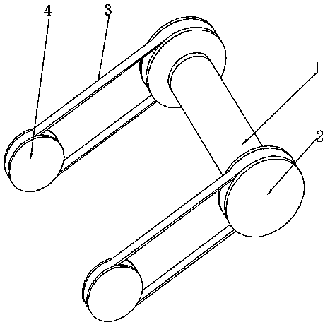
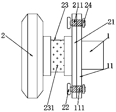
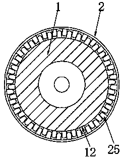
[0024] See Figure 1-4 The present invention provides the following technical solutions: a chain traction device of a chain conveyor, comprising a transmission shaft 1, a sleeve 2, a transmission belt 3 and a transmission wheel 4. The transmission shaft 1 is provided with a protective plate 11 and a gear ring A12 to protect The plate 11 is fixed on the outer wall of the transmission shaft 1, the gear ring A12 is fixed on the outer wall of the transmission shaft 1, the sleeve 2 is provided with a fixing plate 21, bolts 22, nuts 24 and a gear ring B25, and the fixing plate 21 is fixed on the sleeve 2 On one side, the bolt 22 penetrates the fixing plate 21 and is fixed on the protective plate 11, and the nut 24 is fixed on the bolt 22, the gear ring B25 is fixed on the inner wall of the sleeve 2, and one end of the transmission belt 3 is driven on the sleeve 2, and The other end of the driving belt 3 is in driving connection with the driving wheel 4, and the sleeve 2 is in driving...


PUM


Abstract

The invention belongs to the technical field of conveyor conveying, in particular to a chain traction device for a chain conveyor. The chain traction device comprises a transmission shaft, sleeves, transmission belts and transmission wheels, a protective plate and gear rings A are arranged on the transmission shaft, and the protective plate is fixed on the outer wall of the transmission shaft, thegear rings A is fixed on the outer wall of the transmission shaft, fixing plates are fixed on one side of the sleeves, bolts penetrates through the fixing plates to be fixed on the protective plate,nuts are fixed on the bolts, gear rings B is fixed on the inner wall of the sleeves, one end of the transmission belts is transmitted to the sleeves, and the other end of the transmission belts is intransmission connection with the transmission wheels; the sleeves are disassembled by screwing the nuts, the sleeves and the transmission belts are replaced, the transmission shaft is prevented from being disassembled, the structure is simple, the operation is convenient, the time and the labor are saved, the maintenance efficiency is improved, and the slippage and off-line running of the transmission belts in the sleeves is avoided through the groove A.

Description

Technical field [0001] The invention belongs to the technical field of conveyor transportation, and specifically relates to a chain traction device of a chain conveyor. Background technique [0002] The chain conveyor can meet the requirements of single-line conveying of beverage labeling, filling, cleaning and other equipment. It can also make a single line into multiple lines and move slowly, thereby generating storage capacity to meet the needs of sterilization machines, bottle storage stations, and cold bottles. We can make the head and tail of the two chain conveyors into an overlapping mixing chain to make the bottle body in a dynamic transition state, so that the conveyor line does not hold the bottle, which can meet the empty bottle and actual Pressure and pressureless delivery of the bottle. [0003] The traction device of the original chain conveyor is driven by belt and drive shaft. When the belt moves on the drive shaft, the belt rubs the drive shaft. The long-term fri...

Claims


Application Information

Patent Timeline
IPC IPC(8): B65G17/06B65G17/38
CPCB65G17/067B65G17/38
Inventor 徐建红
Owner 安徽华顺智能装备有限公司
Why Eureka
Try Eureka