
Electronic lock

An electronic lock and lock body technology, applied in the field of electronic locks, can solve the problems of reducing the service life of the electromagnet, reducing the security of the lock, reducing the reliability of the lock, etc., so as to improve the locking ability, improve the structural strength, and improve the self-locking ability. Effect

Active Publication Date: 2019-07-19
ZHUHAI PANSHI ELECTRONICS TECH CO LTD
View PDF6 Cites 1 Cited by
  • Summary
  • Abstract
  • Description
  • Claims
  • Application Information

AI Technical Summary

Problems solved by technology

But today's electronic locks are basically simple in structure, small in size, and easy to install, but this type of electronic lock is easily damaged by external shocks, and the security of the lock is low; Ineffective under voltage or strong magnetic environment, thus reducing the security of the lock
In order to ensure the normal operation of the electronic lock, a voltage needs to be applied to the electronic coil during the switch-on period, and there is a large power loss, and it is easy to cause overheating damage if it is powered on for a long time
Or the electromagnet needs to be energized for a long time during the unlocking process, which reduces the service life of the electromagnet, thereby reducing the reliability of the lock

Method used


Image

  • Electronic lock
  • Electronic lock
  • Electronic lock

Examples


Embodiment Construction

[0028] Specific embodiment of electronic lock

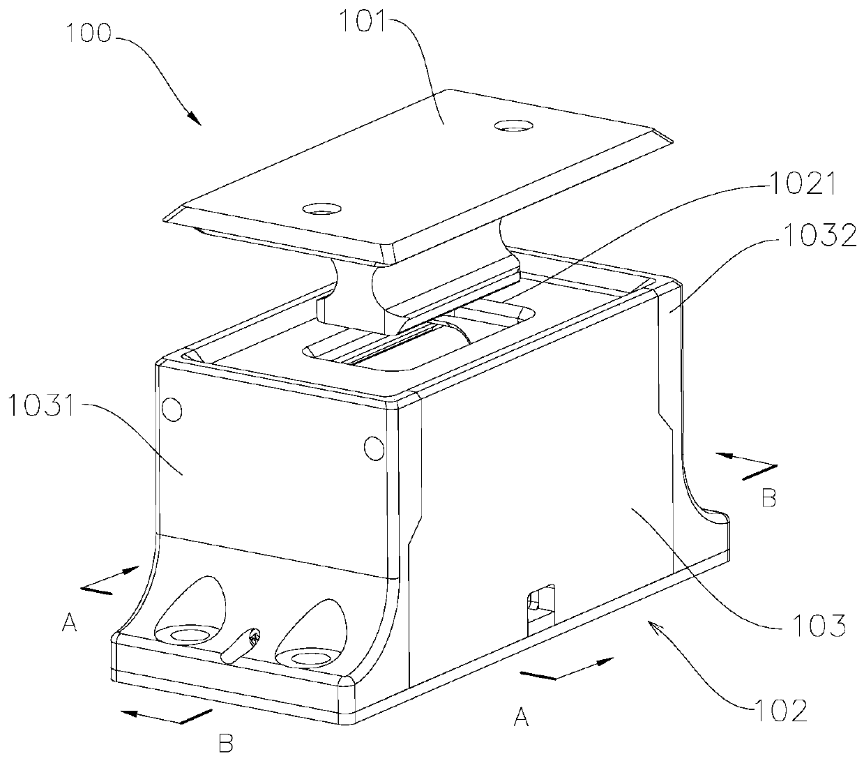
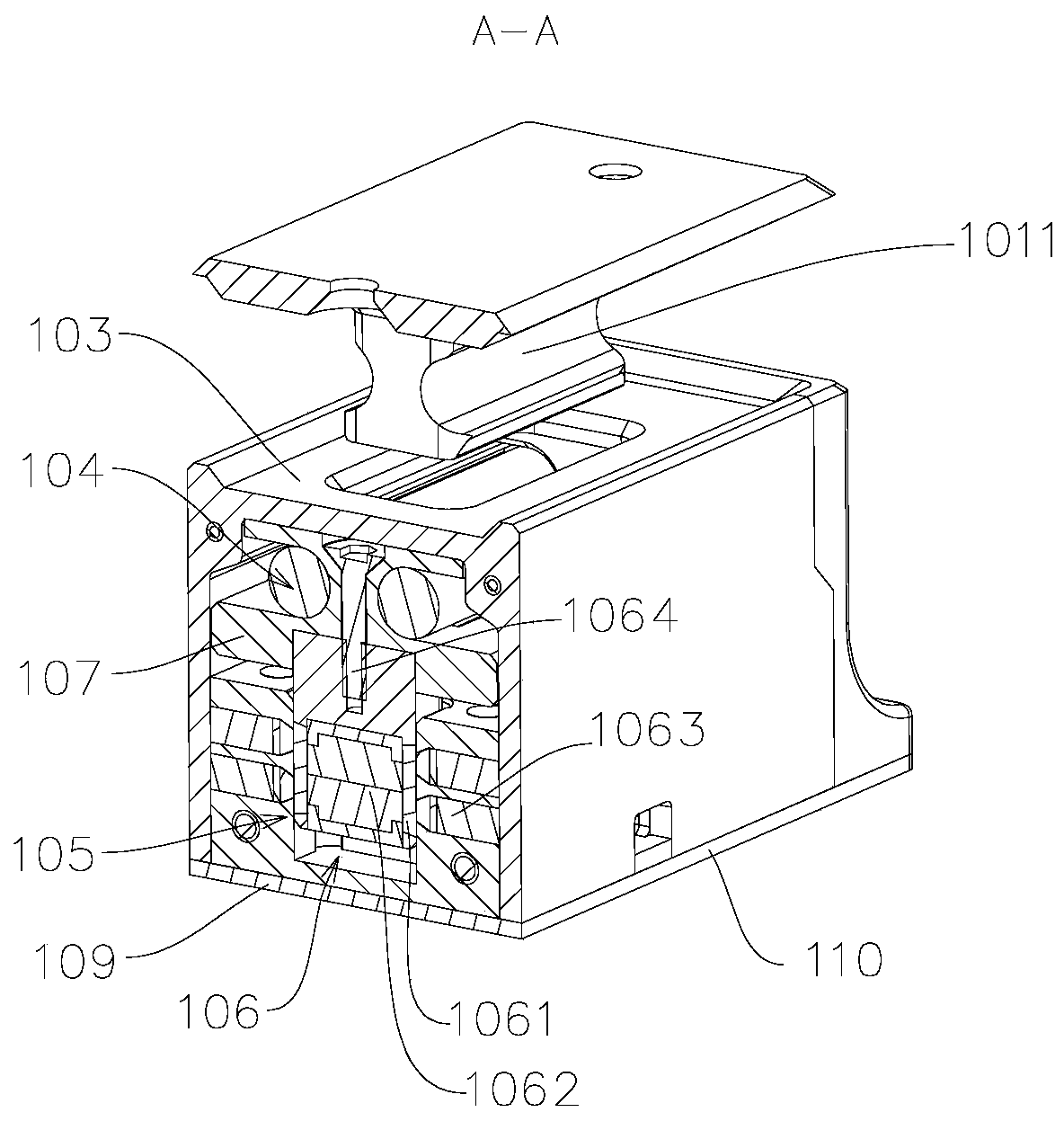
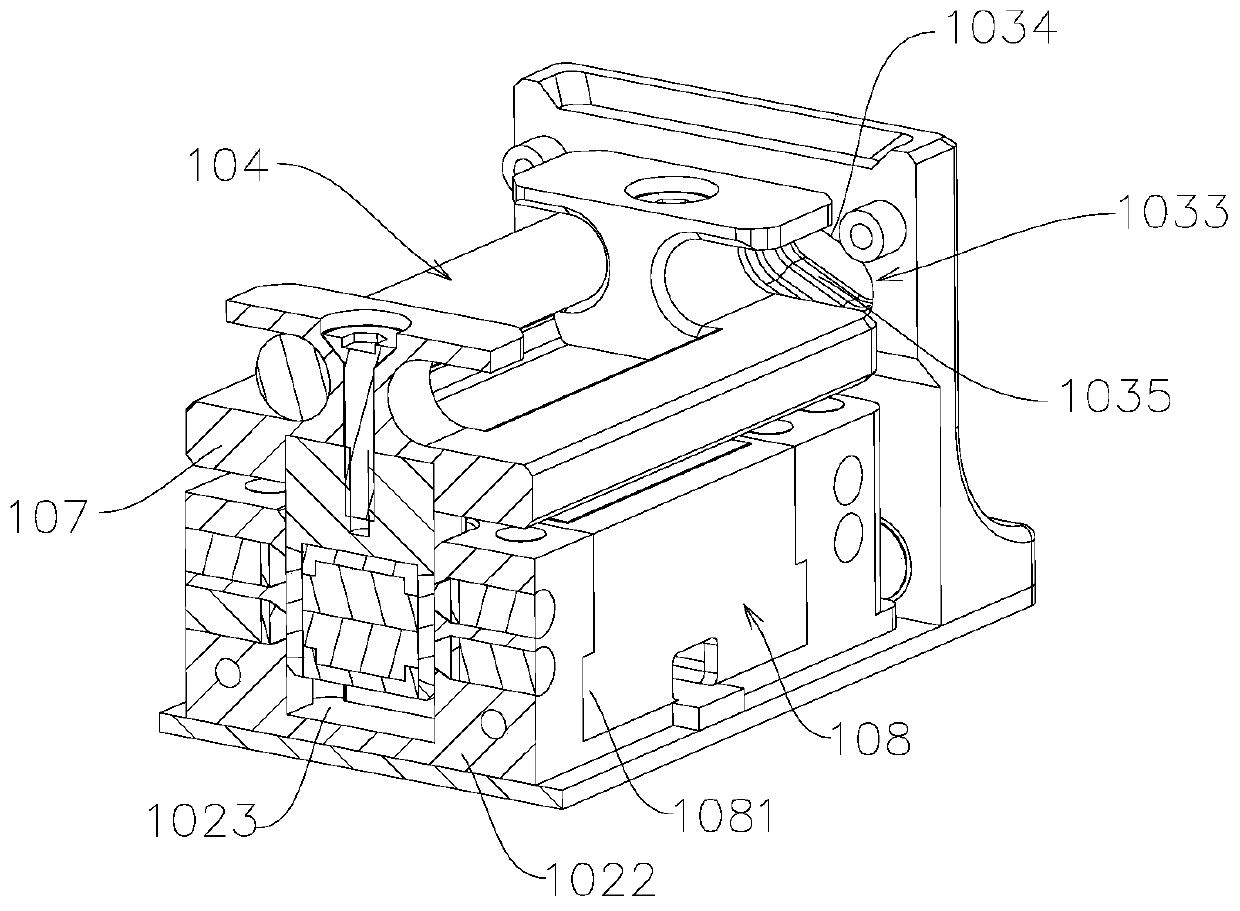
[0029] according to figure 1 , figure 2 In a comprehensive analysis, the electronic lock 100 includes an insert 101 and a lock body 102 . The lock body 102 includes a lock case 103 , a locking member 104 , and a position switching mechanism 105 . The insert 101 can be inserted into the lock body through the lock hole 1021 of the lock body 103 for locking. The end of the electronic lock 100 close to the insert 101 is the top of the electronic lock, and the end away from the insert 101 is the bottom of the electronic lock. Two locking grooves 1011 are arranged symmetrically about the center line in the width direction of the insert 101, and the locking grooves 1011 are preferably arc-shaped locking grooves, which facilitate the locking of the insert 101 between the lock body 102 and the locking groove. The cooperation of the part 104 also facilitates the locking and unlocking of the insert part 101 in the lock body 102 and the...


PUM


Abstract

The invention provides an electronic lock. The electronic lock comprises an insertion part and a lock body, the lock body comprises a lock case, a locking part and a position switching mechanism. Theinserting piece is provided with a locking groove, and the locking piece is symmetrically arranged relative to the center of the inserting piece; the position switching mechanism is used for driving the locking piece to perform position switching between the first working position of the locking and the second working position of the unlocking. When the locking piece is located at the first working position, the locking piece abuts against the retaining working face and the locking groove respectively. When the locking piece is located at the second working position, the locking piece is far away from the locking groove, and the inserting piece can retreat from the lock body. An included angle is formed between the retaining working surface and the central plane of the length direction ofthe electronic lock, and the opening of the included angle towards the bottom part of the lock body. The inclined retaining working surface reduces the damage torque to check the lock hole when the insertion piece is pulled out, so that the self-locking capability of the electronic lock is improved, and the safety of the electronic lock is further improved. The friction force between the locking part and the retaining working surface is reduced, so that the driving force of the locking part is reduced, and the energy is saved.

Description

technical field [0001] The present invention relates to electronic locks. Background technique [0002] Lockset refers to a device that acts as a seal, including locks, keys and accessories. The first locking piece is closely matched with the second locking piece through the lockset, a part of the lockset is installed on the first locking piece, and the other part of the lockset is installed on the second locking piece. The lock can be a door, window, box, etc. Mechanical locks are common locks with simple structure, easy to be opened by foreign objects, and low security; mechanical locks with high security are cumbersome and complicated to unlock, low in convenience, and small in scope of application. [0003] In order to improve the security of the lockset and the convenience of unlocking, various electronic locks appear now. But today's electronic locks are basically simple in structure, small in size, and easy to install, but this type of electronic lock is easily dam...

Claims


Application Information

Patent Timeline
Patent Type & Authority Applications(China)
IPC IPC(8): E05B47/00E05B9/00E05B15/14E05B17/20
CPCE05B9/00E05B15/14E05B47/0001E05B47/0002E05B2047/0092
Inventor 何春旺
Owner ZHUHAI PANSHI ELECTRONICS TECH CO LTD
Features
  • Generate Ideas
  • Intellectual Property
  • Life Sciences
  • Materials
  • Tech Scout
  • Unparalleled Data Quality
  • Higher Quality Content
  • 60% Fewer Hallucinations
Learn More