Camera optics, electronic equipment

A technology of optical mirrors and lenses, applied in optics, optical components, instruments, etc., can solve the problems of lens system enlargement, unfavorable device miniaturization, unsuitable optical systems, etc.

Active Publication Date: 2021-05-04
YUYAO SUNNY OPTICAL INTELLIGENCE TECH CO LTD
View PDF7 Cites 0 Cited by
  • Summary
  • Abstract
  • Description
  • Claims
  • Application Information

AI Technical Summary

Problems solved by technology

However, this wide-angle lens is not suitable for an optical system formed by using a planar image plane for imaging. Even if it can be used, the lens system will become larger, which is not conducive to the miniaturization of the device; and in order to obtain a wide-angle lens with high imaging quality and less distortion , this wide-angle lens is a structural improvement based on "forming an image on an imaging element whose imaging surface has a curved shape with a concave surface facing the object side"
In addition, the invention patent does not further improve the high imaging quality both day and night

Method used


Image

  • Camera optics, electronic equipment
  • Camera optics, electronic equipment
  • Camera optics, electronic equipment

Examples


Embodiment 1

[0078] The specific values ​​of the conditional expression of the imaging optical mirror group of embodiment one are as follows:

[0079] |f1 / f|=7.93

[0080] |f2 / f|+|f3 / f|+|f4 / f|=3.72

[0081] AT1 / (AT1+AT2)=0.86

[0082] |R8 / R9|=2.58

[0083] |MSag8|=0.29

[0084] (V1+V4) / (V2+V3)=0.53

[0085] Then refer to Table 2 and Table 3 below.

[0086]

[0087]

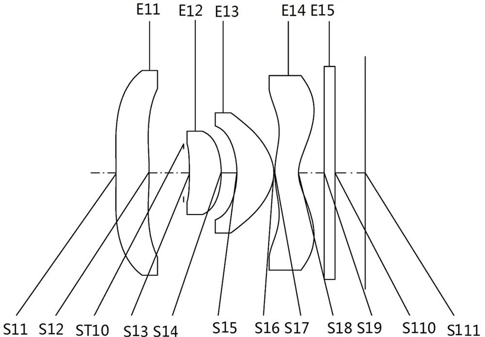
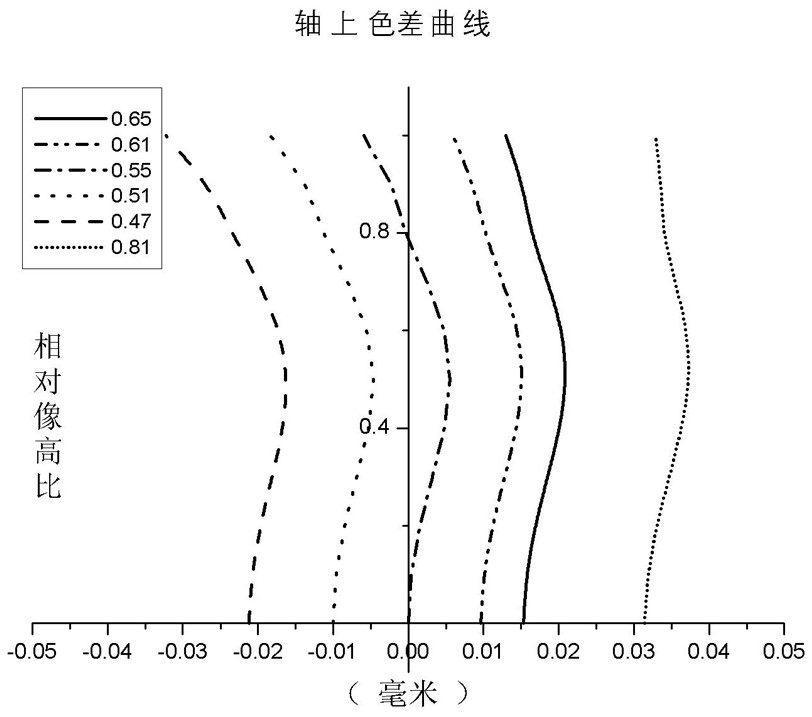
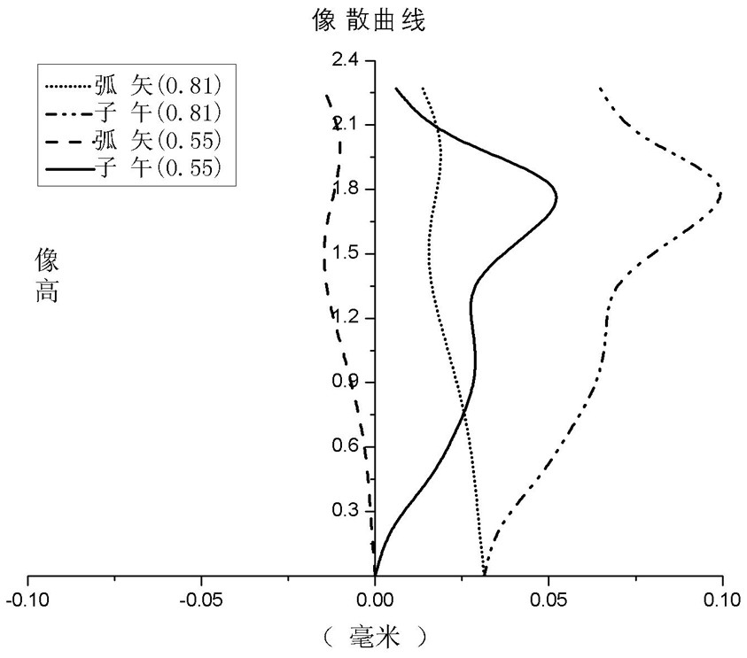
[0088]Table 2 shows the detailed structural data of Embodiment 1 in FIG. 1 , where the units of the radius of curvature, thickness and focal length are mm, and surfaces 0-12 represent surfaces from the object side to the image side in sequence. Table 3 shows the aspheric surface data in Example 1, wherein K represents the cone coefficient in the aspheric surface curve equation, and A4-A14 represent the 4th-16th order aspheric surface coefficients of each surface. In addition, the tables of the following embodiments correspond to the on-axis dispersion diagrams, astigmatism diagrams and distortion diagrams of the re...

Embodiment 2

[0090] The specific values ​​of the conditional expression of the imaging optical mirror group of embodiment two are as follows:

[0091] |f1 / f|=8.58

[0092] |f2 / f|+|f3 / f|+|f4 / f|=3.75

[0093] AT1 / (AT1+AT2)=0.86

[0094] |R8 / R9|=2.69

[0095] |MSag8|=0.3

[0096] (V1+V4) / (V2+V3)=0.53

[0097] Then refer to Table 4 and Table 5 below.

[0098]

[0099]

Embodiment 3

[0101] The specific values ​​of the conditional formula of the imaging optical mirror group of embodiment three are as follows:

[0102] |f1 / f|=8.36

[0103] |f2 / f|+|f3 / f|+|f4 / f|=3.72

[0104] AT1 / (AT1+AT2)=0.85

[0105] |R8 / R9|=2.66

[0106] |MSag8|=0.3

[0107] (V1+V4) / (V2+V3)=0.53

[0108] Then refer to Table 6 and Table 7 below.

[0109]

[0110]


PUM


Abstract

An imaging optical lens group and electronic equipment belong to the technical field of imaging optical devices. The imaging optical lens group of the present invention includes sequentially from the object side to the image side along the optical axis: a first lens with positive refractive power, and the object side of the first lens is concave at the near optical axis; a second lens; three lenses with positive refractive power; and a fourth lens with negative refractive power, the lateral side of the fourth lens is concave at the near optical axis; wherein the first lens and the fourth lens are concave at the near optical axis; A diaphragm is arranged between the two lenses; the object side surface and the image side surface of the first lens, the second lens, the third lens, and the fourth lens are all aspherical surfaces. The electronic device of the present invention includes the above-mentioned imaging optical lens group. While achieving good imaging quality, the present invention has the performances of miniaturization, large field of view, small distortion, day and night confocal and the like.

Description

technical field [0001] The invention belongs to the technical field of imaging optical devices, and in particular relates to an imaging optical mirror group and electronic equipment. Background technique [0002] With the development of computer, modern integrated manufacturing, modern information and other technologies, intelligent vision has entered a stage of vigorous development, and the optical system, as the information acquisition front end of intelligent vision, is the basis of intelligent vision. With the improvement of semiconductor process technology, not only higher requirements are put forward for the miniaturization of the optical system, but also the imaging quality requirements of the optical system in different wavelength bands are also increasing, especially the optical system is required to have a larger field of view, smaller The distortion provides a more realistic and richer information basis for the subsequent image processing of intelligent vision. ...

Claims


Application Information

Patent Timeline
Patent Type & Authority Patents(China)
IPC IPC(8): G02B13/00G02B13/06
CPCG02B13/004G02B13/06
Inventor 杜佳玮
Owner YUYAO SUNNY OPTICAL INTELLIGENCE TECH CO LTD
Why Eureka
Try Eureka