Multi-core processor and fault injection method thereof

A technology of multi-core processor and fault injection, which is applied in the direction of electrical digital data processing, detecting faulty computer hardware, using fault dictionary to detect faulty hardware, etc. It can solve problems such as voltage influence and error, and achieve the effect of reducing the impact

Active Publication Date: 2019-07-19
TSINGHUA UNIV
View PDF5 Cites 0 Cited by
  • Summary
  • Abstract
  • Description
  • Claims
  • Application Information

AI Technical Summary

Problems solved by technology

In DVFS, the frequency of processor cores is independent, but all cores share the same hardware voltage manager. In a multi-core processor supporting DVFS, the voltage of each core is the same. If the fault is realized by reducing

Method used


Image

  • Multi-core processor and fault injection method thereof
  • Multi-core processor and fault injection method thereof
  • Multi-core processor and fault injection method thereof

Examples


Embodiment 1

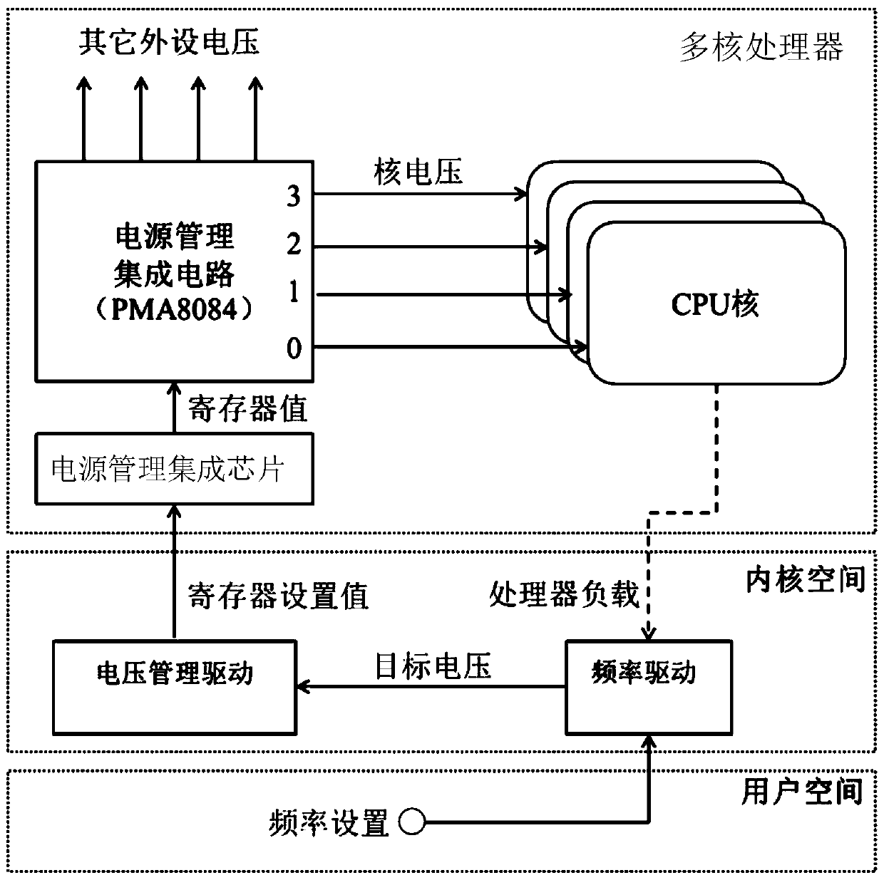
[0051] Based on the above modification to the voltage management driver, this application provides a frequency-voltage difference fault injection method based on a multi-core processor. When a hardware fault needs to be injected into a certain processor core, the processor core is designated as the attacked core , Bind the attacked program to the attacked core for execution, the processor core running the attacking program is used as the attacking core, and other processor cores are used as other unrelated cores. Therefore, the attacking core running the attacking program can be used The designated program injects hardware faults into the attacked core, and does not affect the normal operation of other unrelated cores and programs on them.

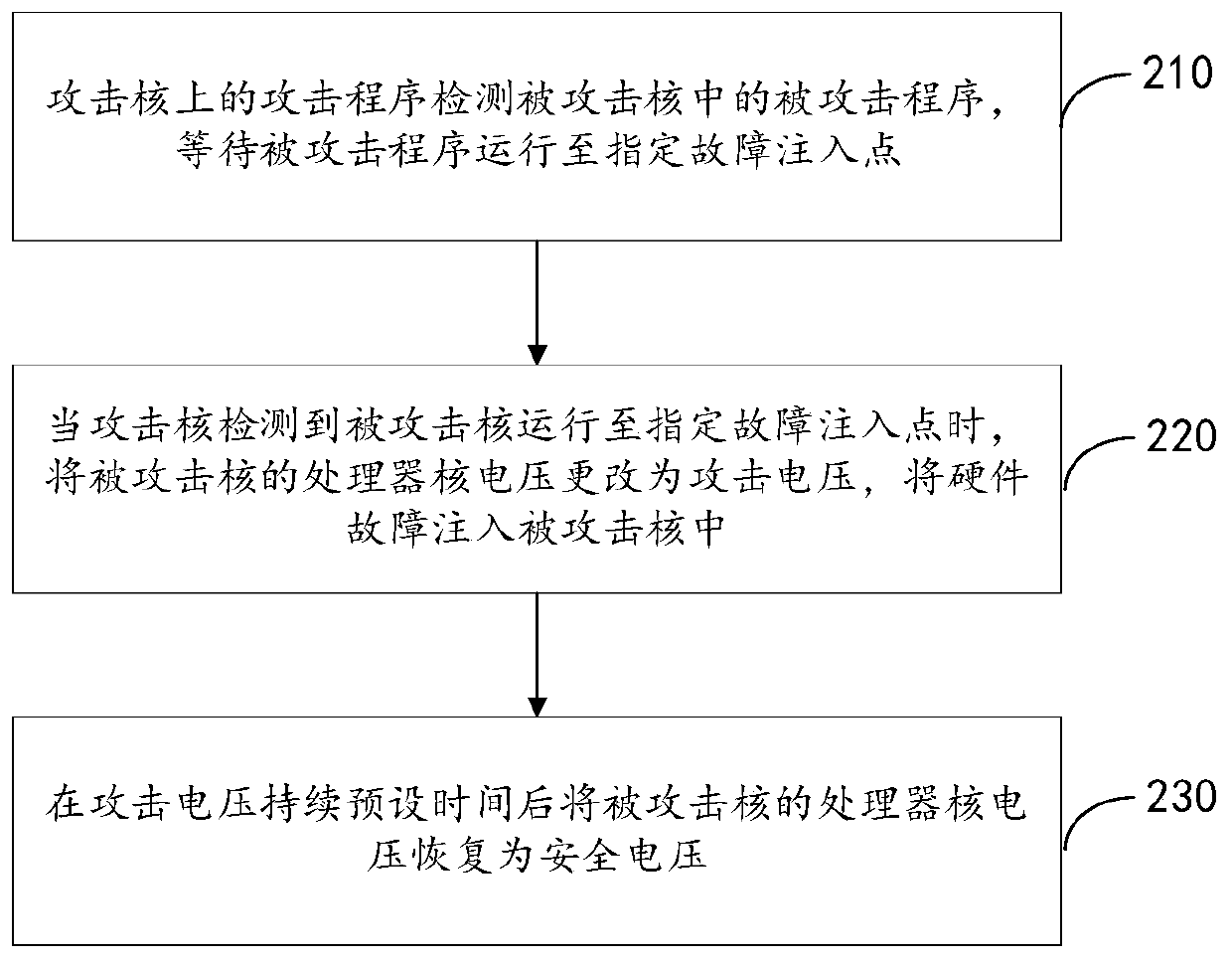
[0052] In this embodiment, the attack program running on the attacking core has a fault injection method for the attacked core as follows: figure 2 Shown, including:

[0053] Step 210: The attack program on the attacking core detects the attac...

Embodiment 2

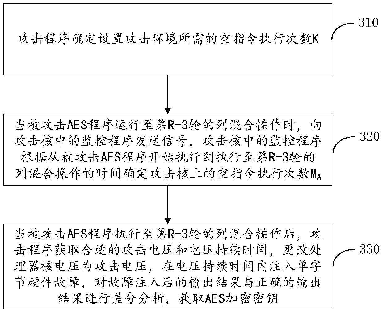
[0067] On the basis of the modification of the voltage management driver program of the embodiment to realize the hardware fault injection through the frequency-voltage difference, the second embodiment of the present application takes the AES encryption key obtained in the AES encryption program as an example to illustrate, the second embodiment includes: image 3 As shown to obtain the AES encryption key in the ordinary world and as Figure 4 Obtain the AES encryption key in TrustZone as shown;

[0068] Taking the designated fault injection point as inputting a single-byte fault in the R-2 round of the AES encryption program as an example, in order to make the input of the R-2 round of the AES encryption program a single-byte fault, the fault injection point is controlled In the R-3 round of column mixing operations.

[0069] image 3 In order to obtain the method flow chart of the AES encryption key in the ordinary world through frequency-voltage difference based fault injection,...

Embodiment 3

[0091] The third embodiment of this application provides a verification experiment in which a processor based on the ARM Krait architecture injects hardware faults into the AES encryption program to obtain the AES encryption key:

[0092] Image 6 Shown is the relationship diagram between the number of executions and the frequency of empty instructions required to wait for the attacked function to start executing. Among them, the frequency of the attack core is set to 0.42GHz, and the attack voltage is set to 0.6V. Image 6 It can be seen that the frequency affects the execution speed of the attacking core and the attacked core. When the attacking core frequency and the processor core voltage remain unchanged, the greater the frequency of the attacked core, the shorter the waiting time for the attacked function to start execution.

[0093] Figure 7 It shows the relationship between the number of executions and the frequency of the empty instructions required from the execution of t...


PUM


Abstract

The invention discloses a multi-core processor and a fault injection method thereof, and relates to the field of computer processors. The fault injection method disclosed by the invention comprises the following steps: when a hardware fault needs to be injected into a certain processor core of a multi-core processor, appointing the processor core as an attacked core, and taking another certain processor core as an attacking core; when the attacking core detects that the attacked core runs to an appointed fault injection point, changing the processor core voltage of the attacked core into an attacking voltage, and injecting a hardware fault into the attacked core; and recovering the processor core voltage of the attacked core to the safety voltage after the attacking voltage lasts for a preset time. According to the fault injection method provided by the invention, on the basis of not changing other nuclear voltages, other cores except the attack core and the attacked core are not influenced, and hardware fault injection is realized, so that the purpose of loading an untrusted application program into a security environment is achieved.

Description

Technical field [0001] This application relates to the field of computer processors, and in particular to a multi-core processor and a fault injection method thereof. Background technique [0002] With the rapid development of semiconductor technology, very large scale integrated circuits, and computer architecture, the average instruction throughput rate of processors has been greatly improved. However, how to reduce the energy consumption of processors has always been a problem that needs to be considered, especially On mobile devices such as mobile phones, laptops, and tablets. The energy consumption of the processor is the convolution of dynamic power consumption in time. The dynamic power consumption is determined by the load capacitance C, voltage V, and frequency F. The relationship is as follows: [0003] P=V 2 ×F×C [0004] Dynamic power consumption is proportional to voltage and frequency. Therefore, reducing the processor core voltage and frequency can reduce the dynamic...

Claims


Application Information

Patent Timeline
IPC IPC(8): G06F11/22G06F11/26G06F15/177
CPCG06F11/2236G06F11/2252G06F11/26G06F15/177
Inventor 汪东升吕勇强邱朋飞王淳
Owner TSINGHUA UNIV
Why Eureka
Try Eureka