Supercharge Your Innovation With Domain-Expert AI Agents!

Shaft sealing device and rotating electrical machine

A technology for rotating electrical machines and shaft seals, which is used in electromechanical devices, cooling/ventilation devices, mechanical equipment, etc., and can solve the problems of insufficient cooling gas sealing and low followability.

Active Publication Date: 2021-03-12
KK TOSHIBA +1
View PDF7 Cites 0 Cited by
  • Summary
  • Abstract
  • Description
  • Claims
  • Application Information

AI Technical Summary

Problems solved by technology

That is, the followability of the body outer gasket member 30b is lower than that of the body inner gasket member 30a.
As a result, there are cases where the gas seal for cooling is insufficient
In particular, this problem becomes more prominent as cooling gas is pressurized

Method used


Image

  • Shaft sealing device and rotating electrical machine
  • Shaft sealing device and rotating electrical machine
  • Shaft sealing device and rotating electrical machine

Examples


no. 1 Embodiment approach >

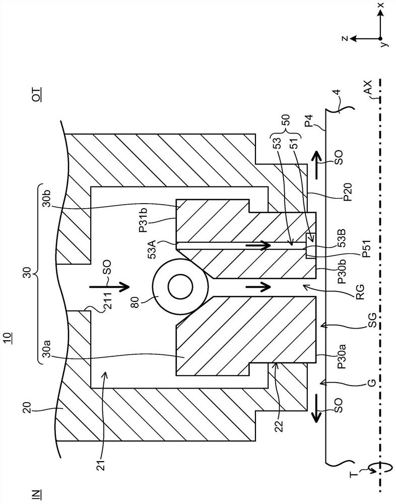
[0051] use figure 1 , figure 2 with image 3 The shaft seal device 10 according to the first embodiment will be described.

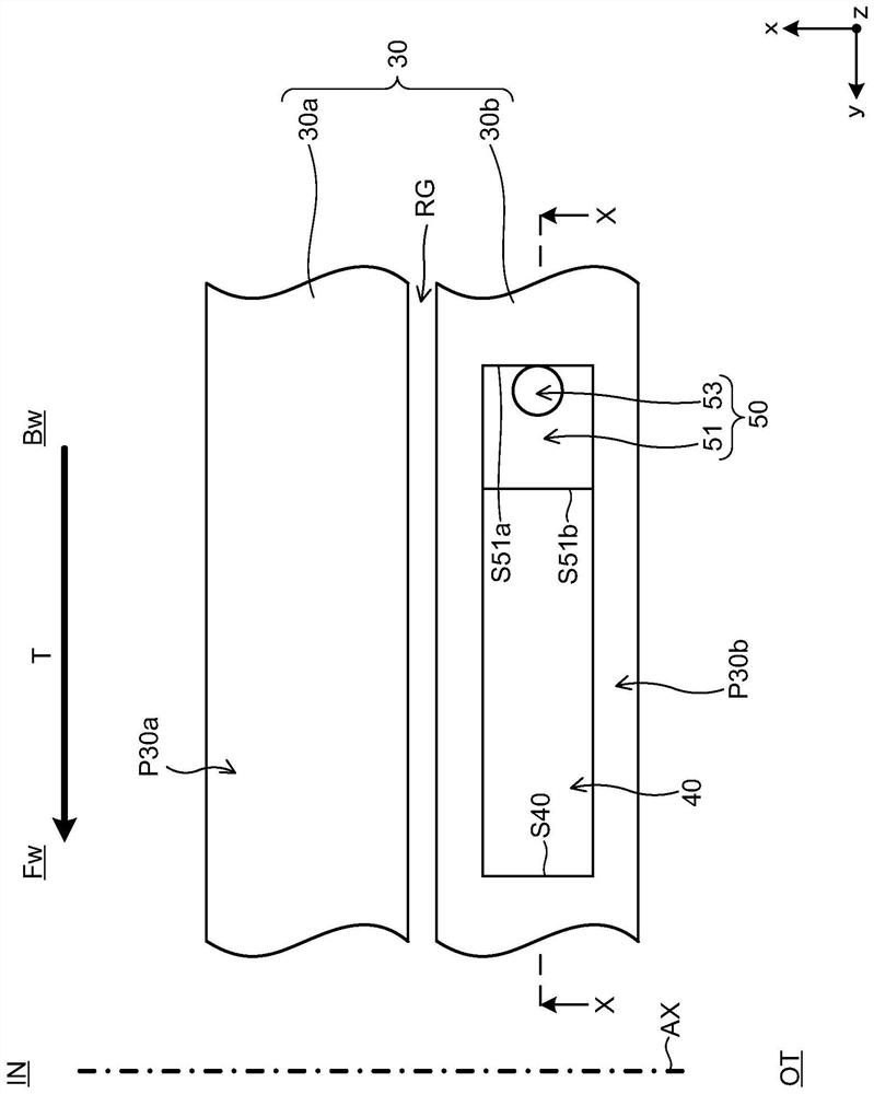
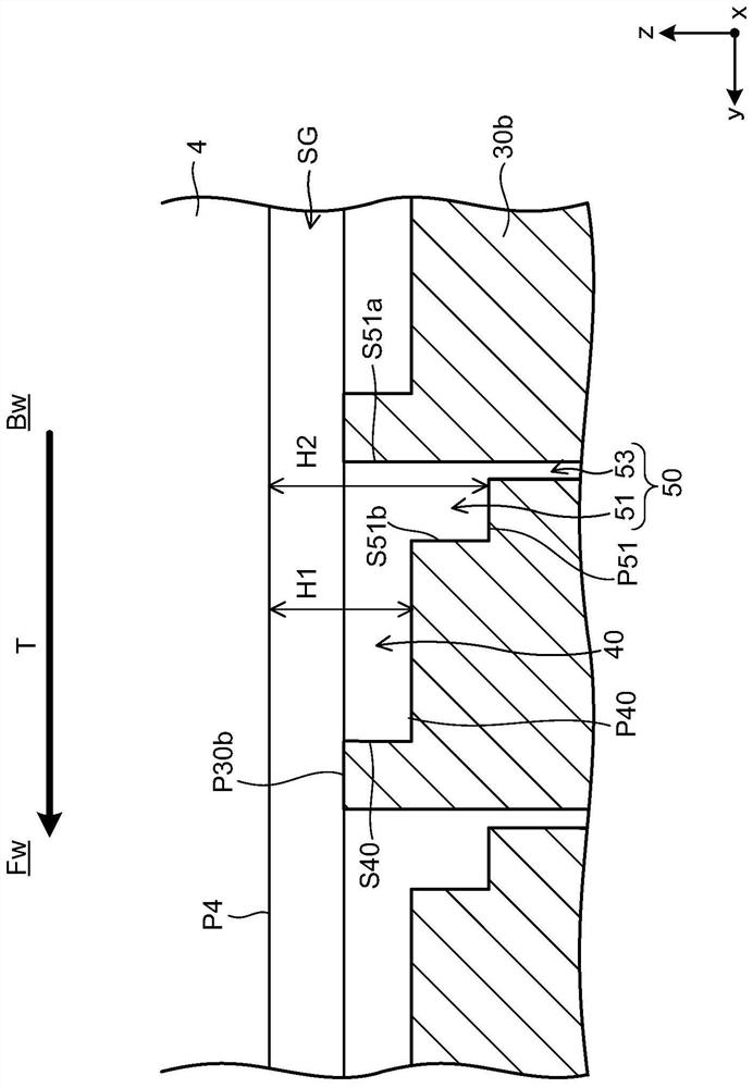
[0052] figure 1 and Figure 13 Similarly, a vertical plane (xz plane) cross section is shown for the shaft seal device 10 . figure 2 The inner peripheral surface of the seal ring 30 constituting the shaft sealing device 10 is shown. exist figure 2 Here, the longitudinal direction substantially corresponds to the axial direction (x) along the rotation center axis AX, and the upper side is the body inner side IN, and the lower side is the body outer side OT. and, figure 2 The middle lateral direction substantially corresponds to the rotation direction T, and the left side is the front side Fw of the rotation direction T, and the right side is the rear side Bw. image 3 For the shaft seal device 10, the figure 2 The cross-section of the XX-X part. image 3 Among them, the longitudinal direction substantially corresponds to the radial direct...

no. 2 Embodiment approach >

[0082] use Figure 7 The shaft seal device 10 according to the second embodiment will be described. Figure 7 neutralize figure 2 Similarly, the inner peripheral surface of the seal ring 30 constituting the shaft seal device 10 is shown.

[0083] Such as Figure 7 As shown, part of the form of the inner peripheral surface P30b of the body-external side gasket member 30b in the gasket 30 of this embodiment is similar to that of the first embodiment (see figure 2 )different. Except for this point and related points, this embodiment is the same as that of the first embodiment, and thus description thereof will be appropriately omitted.

[0084]In this embodiment, an oil discharge groove 45 is formed on the inner peripheral surface P30b of the body outer packing member 30b. The oil discharge groove 45 communicates with the groove 40 on the front side Fw of the groove 40 in the rotational direction T. As shown in FIG. The oil discharge groove 45 is configured to discharge t...

no. 3 Embodiment approach >

[0093] use Figure 9 with Figure 10 The shaft seal device 10 according to the third embodiment will be described. Figure 9 neutralize figure 1 Likewise, the shaft seal device 10 shows a cross section on a vertical plane (xz plane). Figure 10 neutralize figure 2 Similarly, the inner peripheral surface of the seal ring 30 constituting the shaft seal device 10 is shown.

[0094] Such as Figure 9 with Figure 10 As shown, part of the form of the inner peripheral surface P30b of the body-external side gasket member 30b in the gasket 30 of this embodiment is similar to that of the first embodiment (see figure 1 with figure 2 )different. Except for this point and related points, this embodiment is the same as that of the first embodiment, and thus description thereof will be appropriately omitted.

[0095] In the present embodiment, the oil discharge port 46 is formed in a portion of the inner peripheral surface P30b of the body-outside gasket member 30b that is loca...


PUM


Abstract

The present invention provides a shaft seal device and the like capable of effectively sealing cooling gas. The seal ring in the shaft seal device according to the embodiment includes a body inner seal member and a body outer seal member located on the outer side of the rotary electric machine casing than the body inner seal member in the axial direction of the rotating shaft. An annular gap exists between the body inner sealing ring part and the body outer sealing ring part. At the same time, there are sealing gaps between the inner peripheral surface of the body inner sealing ring member and the outer peripheral surface of the rotating shaft and between the inner peripheral surface of the body outer sealing ring member and the outer peripheral surface of the rotating shaft. The inner peripheral surface of the body inner sealing ring member is a flat surface along the outer peripheral surface of the rotating shaft as a whole, and a groove extending along the rotation direction of the rotating shaft is formed on the inner peripheral surface of the body outer sealing ring member.

Description

technical field [0001] Embodiments of the present invention relate to a shaft seal device and a rotating electric machine. Background technique [0002] A rotating electrical machine is a device such as a turbo generator, and is configured such that a rotor rotates inside a stator. In a rotating electric machine such as a turbo generator, for example, hydrogen gas is sealed inside, and the sealed hydrogen gas is used as a cooling gas for cooling a rotor and a stator. A rotating electric machine is provided with a shaft seal device in order to prevent cooling gas such as hydrogen gas from leaking to the outside. [0003] use Figure 12 A rotating electric machine 1 according to the related art will be described. exist Figure 12 Here, the horizontal direction is a horizontal direction (x), and actually corresponds to an axial direction along the rotation center axis AX of the rotor constituting the rotary electric machine 1 . and, in Figure 12 Among them, the longitudinal...

Claims


Application Information

Patent Timeline
Patent Type & Authority Patents(China)
IPC IPC(8): H02K9/12H02K5/15F16J15/40
CPCF16J15/40H02K5/15H02K9/12F16J15/441H02K5/124H02K9/08F16J15/162F16J15/32H02K7/1823
Inventor 平野俊夫金崎丈池田和德千叶英树吉水谦司
Owner KK TOSHIBA
Features
  • R&D
  • Intellectual Property
  • Life Sciences
  • Materials
  • Tech Scout
  • Unparalleled Data Quality
  • Higher Quality Content
  • 60% Fewer Hallucinations
Learn More