
Camera module and terminal

A camera module and terminal technology, applied in image communication, TV, color TV components and other directions, can solve the problems of high production cost, inconvenient dispensing operation, etc., and achieve the advantages of convenient operation, enhanced stability and reduced production cost. Effect

Pending Publication Date: 2019-07-19
KUNSHAN Q TECH CO LTD
View PDF6 Cites 5 Cited by
  • Summary
  • Abstract
  • Description
  • Claims
  • Application Information

AI Technical Summary

Problems solved by technology

However, in the assembly process, dispensing equipment and glue curing equipment are required, the production cost is high, and the dispensing operation is inconvenient

Method used


Image

  • Camera module and terminal
  • Camera module and terminal
  • Camera module and terminal

Examples


Embodiment Construction

[0022] The specific implementation manners of the present invention will be further described in detail below in conjunction with the accompanying drawings and embodiments. The following examples are used to illustrate the present invention, but are not intended to limit the scope of the present invention.

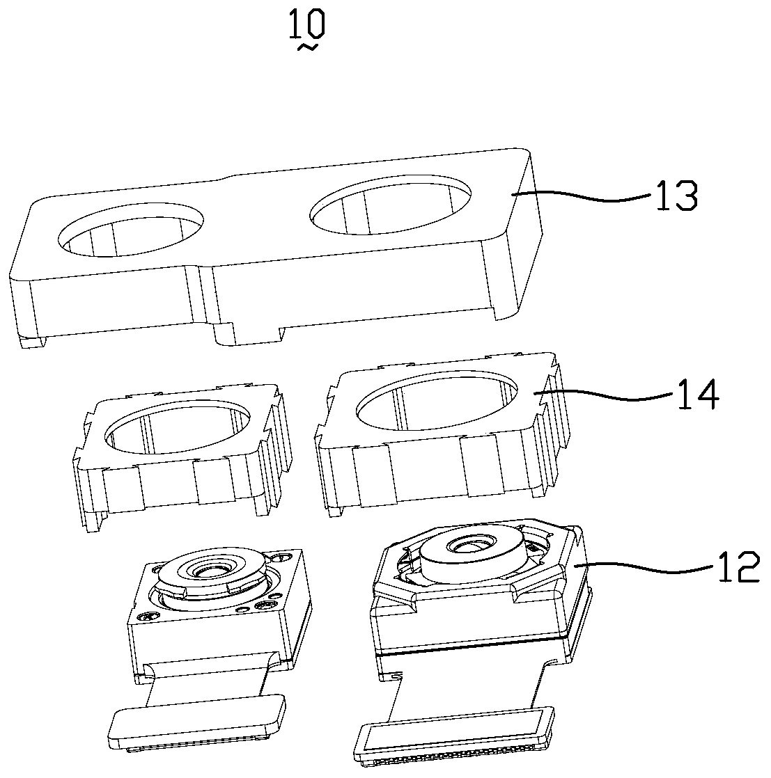
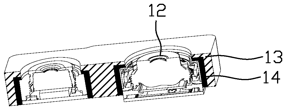
[0023] figure 1 It is an exploded view of a camera module according to an embodiment of the present invention. figure 2 for figure 1 Schematic diagram of the cross-sectional structure. Such as figure 1 and figure 2 As shown, the camera module 10 includes two lenses 12, a fixed bracket 13 and two elastic elements 14, the elastic element 14 is arranged in the fixed bracket 13, and is connected with the fixed bracket 13, the lens 12 is arranged in the elastic element 14, and the lens 12 is fixedly connected with elastic element 14.

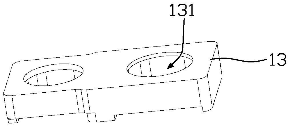
[0024] image 3 It is a structural schematic diagram of a fixing bracket according to an embodiment of the present invention. Figure ...


PUM


Abstract

A camera module includes a lens and also comprises a fixing bracket and an elastic element; the fixing bracket comprises a first containing space, the elastic element comprises a second containing space and a limiting protrusion, the elastic element is arranged in the first containing space and connected with the fixing bracket, the lens is fixed in the second containing space, and the limiting protrusion is arranged on the inner wall of the second containing space and makes contact with the outer wall of the lens. According to the camera module, dispensing equipment and glue curing equipmentcan be omitted, the production cost is reduced, and the fixing mode is convenient. The invention also relates to a terminal.

Description

technical field [0001] The invention relates to the technical field of imaging equipment, in particular to a camera module and a terminal. Background technique [0002] At present, during the assembly process of dual cameras and multi-camera modules, the lens is usually bonded to a metal or plastic fixing bracket by dispensing glue, so as to realize the fixing of the lens and the fixing bracket. However, glue dispensing equipment and glue curing equipment need to be used in the assembly process, the production cost is high, and the glue dispensing operation is inconvenient. [0003] The foregoing description is provided to provide general background information and does not necessarily constitute prior art. Contents of the invention [0004] The purpose of the present invention is to provide a camera module and terminal, which can save the use of glue dispensing equipment and glue curing equipment, reduce production costs, and the fixing method is convenient. [0005] A ...

Claims


Application Information

Patent Timeline
Patent Type & Authority Applications(China)
IPC IPC(8): H04N5/225
CPCH04N23/57H04N23/55
Inventor 许杨柳邓爱国顾军金元斌
Owner KUNSHAN Q TECH CO LTD
Learn More