
An automatic pressing device

A technology of pressing device and driving device, applied in the direction of transformer/inductor coil/winding/connection, etc., can solve the problems of easy loosening of windings, poor short-circuit resistance of transformers, easy loosening of coils, etc. Short-circuit capability, the effect of ensuring quality

Active Publication Date: 2016-08-17
SUZHOU ZHONGTUO PATENT OPERATION MANAGEMENT CO LTD
View PDF5 Cites 0 Cited by
  • Summary
  • Abstract
  • Description
  • Claims
  • Application Information

AI Technical Summary

Problems solved by technology

Due to the unreasonable structure of the previous transformers, the windings are easy to loose, and the coils are easy to loosen, resulting in poor short-circuit resistance of the transformer and affecting the normal operation of the entire electronic system.

Method used


Image

  • An automatic pressing device
  • An automatic pressing device
  • An automatic pressing device

Examples


Embodiment Construction

[0015] The present invention is described below in conjunction with accompanying drawing.

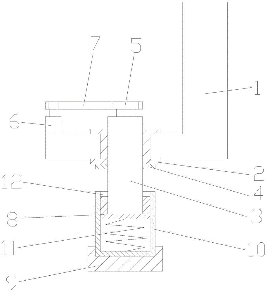
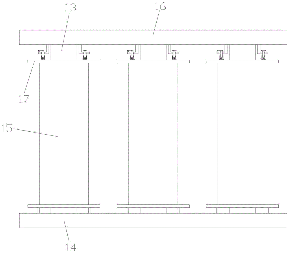
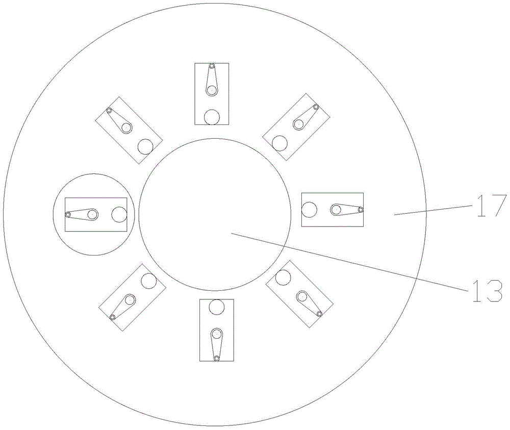
[0016] as attached figure 1 The shown automatic pressing device of the present invention includes a fixed frame 1, a threaded sleeve 2, a screw rod 3, a lock nut 4, a driving disc 5, a driving device 6, a belt 7, a slider 8, and a fixed block 9 , sliding sleeve 10 and elastic parts; the fixed frame 1 is provided with a threaded sleeve 2; the screw 3 passes through the threaded sleeve 2; the screw 3 is covered with a lock nut 4; the lock nut 4 is located on the thread Below the cover 2; the top of the screw 3 is provided with a driving disc 5; the driving device 6 is arranged on the fixed frame 1; the output end of the driving device 6 is connected with the driving disc 5 through a belt 7; The bottom is provided with a slider 8; the slider 8 slides on the sliding sleeve 10; the sliding sleeve 10 is fixed in the fixed block 9; an elastic member is provided between the bottom of the slidi...


PUM


Abstract

The invention discloses an automatic pressing device which comprises a fixed frame, a thread bushing, a screw rod, a locknut, a drive plate, a drive device, a belt, a sliding block, a fixed block, a sliding sleeve and a flexible assembly. The thread bushing is arranged in the fixed frame; the screw rod penetrates through the thread bushing; the screw rod is sleeved with the locknut; the locknut is located on the lower side of the thread bushing; the drive plate is arranged on the top of the screw rod; the drive device is arranged on the fixed frame; the output end of the drive device is connected with the drive plate through the belt; the sliding block is arranged at the bottom of the screw rod; the sliding block slides in the sliding sleeve; the sliding sleeve is fixed in the fixed block; the flexible assembly is arranged between the bottom of the sliding block and the internal bottom surface of the sliding sleeve. The automatic pressing device can apply pressure to an object below the fixed block continuously, semi-automatic operation is achieved, no manual operation is needed, and convenience and rapidness are achieved.

Description

technical field [0001] The invention relates to an automatic compacting device, in particular to an automatic compacting device which can be used in high-voltage transformers. Background technique [0002] With the development of power technology, the capacity of transformers is getting larger and higher, and the voltage level is getting higher and higher. The role of high-voltage transformers in power systems is prominent. Therefore, the safe operation of high-voltage transformers is related to the overall situation of electronic systems. The safe operation of high-voltage transformers is affected by many factors, among which the anti-short circuit performance is one of the most important. The safe operation of high-voltage transformers is affected by many factors, among which the anti-short circuit performance is one of the most important. Due to the unreasonable structure of the previous transformers, the windings are easy to loose, and the coils are easy to loosen, res...

Claims


Application Information

Patent Timeline
Patent Type & Authority Patents(China)
IPC IPC(8): H01F27/30
Inventor 钱永清
Owner SUZHOU ZHONGTUO PATENT OPERATION MANAGEMENT CO LTD
Learn More