Sliding stop structure

A stop and slip technology, applied in special positions of vehicles, vehicle seats, vehicle parts, etc., can solve problems such as inability to effectively provide stop resistance, large layout space requirements, and complex slide rail structures. Conducive to handling, strong structural tolerance, and the effect of enhancing the sense of control

Active Publication Date: 2019-07-23
DONGFENG MOTOR CORP HUBEI
View PDF5 Cites 0 Cited by
  • Summary
  • Abstract
  • Description
  • Claims
  • Application Information

AI Technical Summary

Problems solved by technology

However, since the extrusion force provided by the metal reed is gradually attenuated after long-term compression and deformation, the sliding force gradually decreases, and it cannot effectively provide stop resistance at any position; at the same time, in the sliding process, only relying on the metal The friction between the reed and the chute provides a sense of sliding damping. At the start and end positions of sliding, the sliding resistance needs to gradually increase until it stops completely. This structure has a poor sense of stopping
On the other hand, the structure of the whole set of slide rails of the handrail is relatively complicated, and the Z-direction layout requires a large space

Method used


Image

  • Sliding stop structure
  • Sliding stop structure
  • Sliding stop structure

Examples


Embodiment Construction

[0024] The present invention will be further described in detail below in conjunction with the accompanying drawings to facilitate a clearer understanding of the present invention, but they do not limit the present invention.

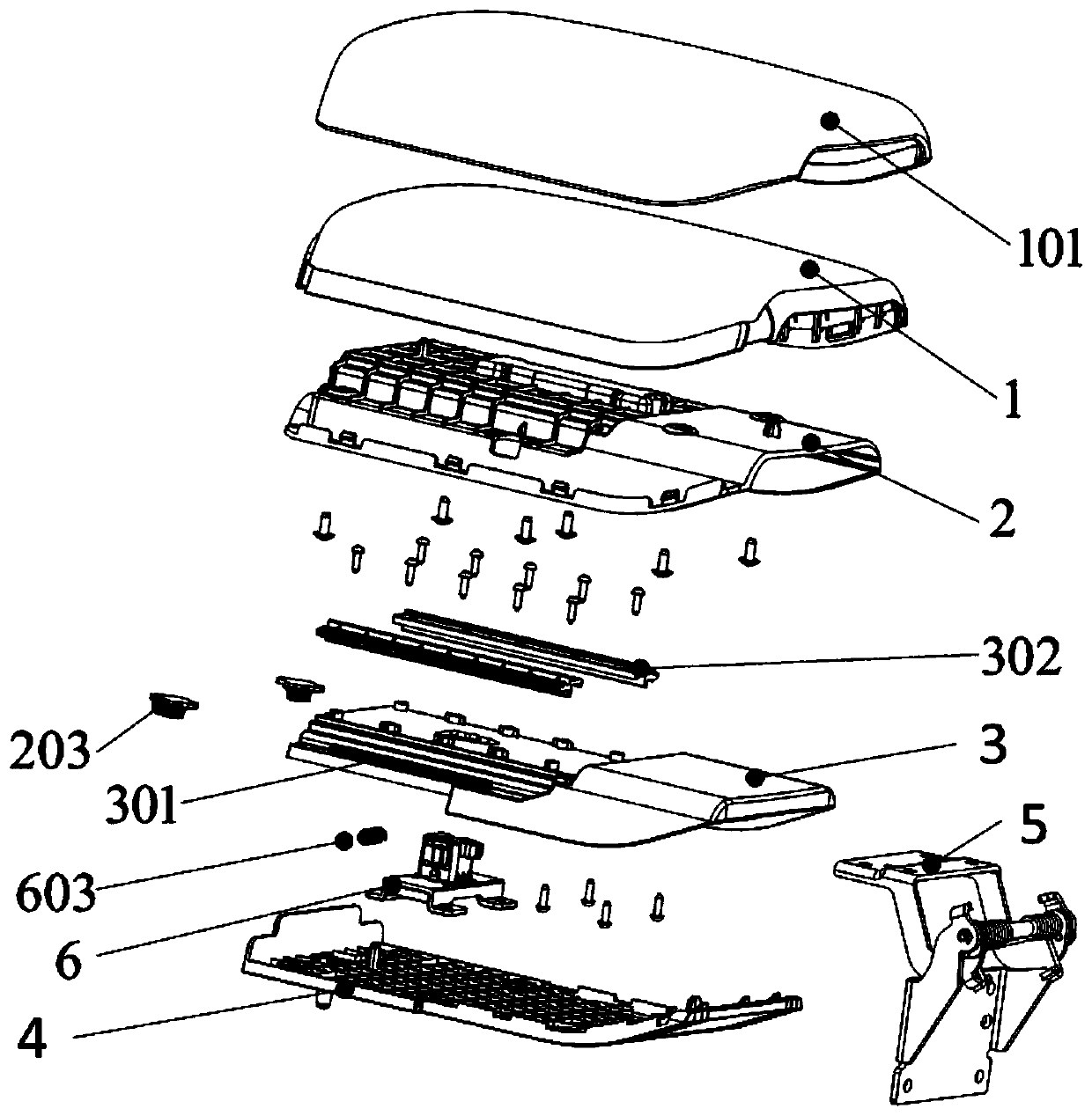
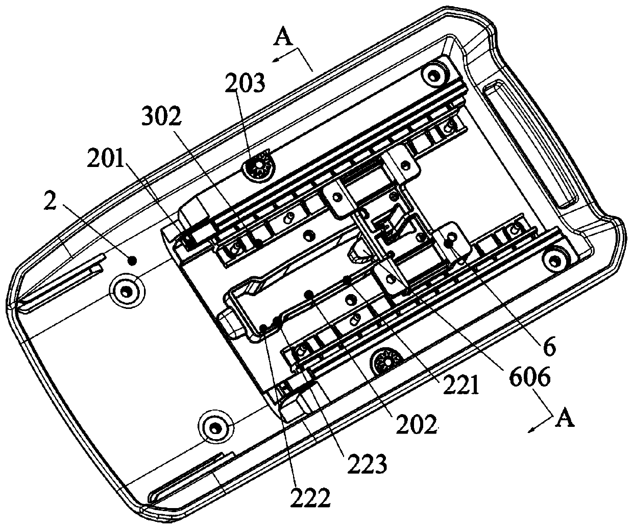
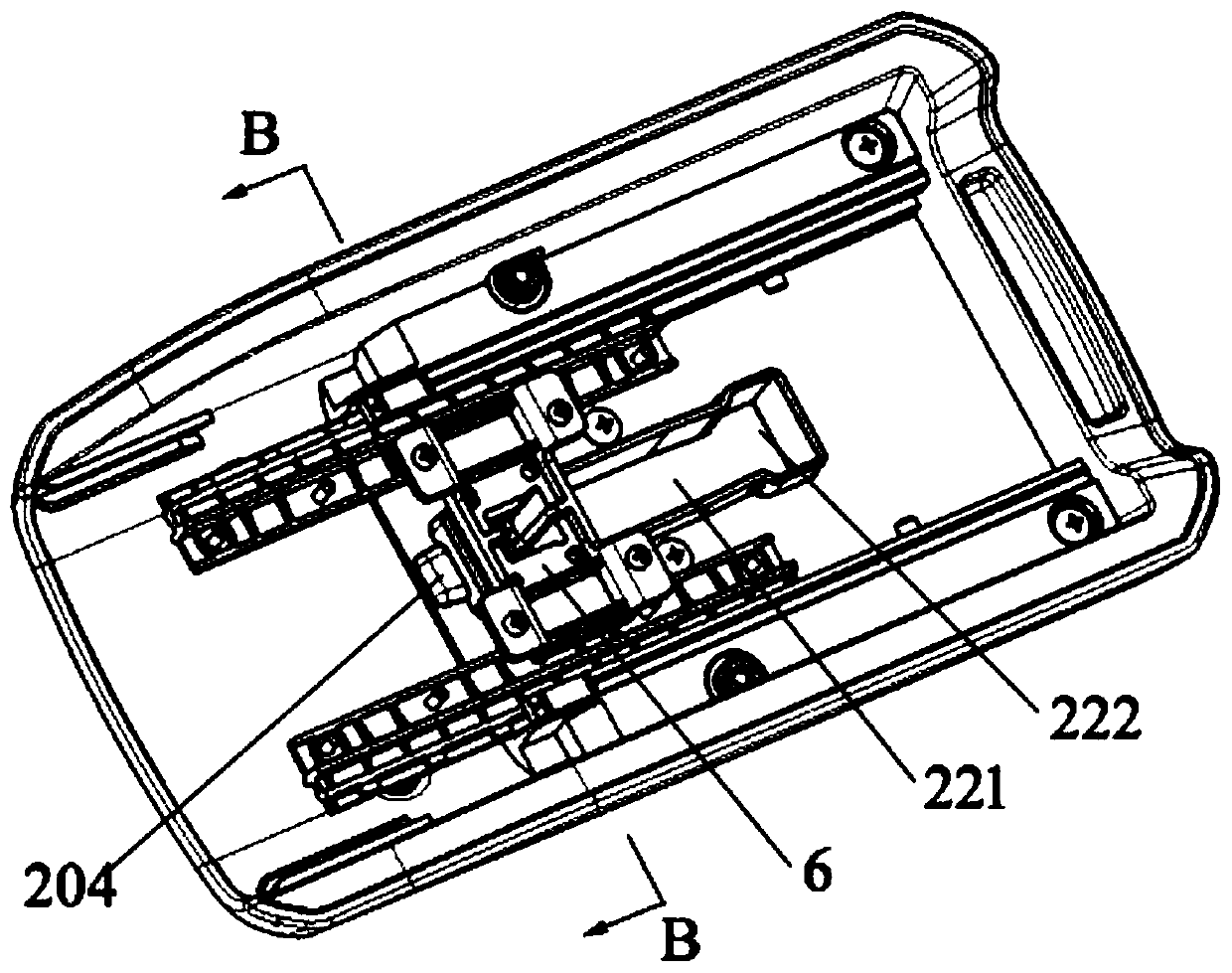
[0025] Such as Figure 1-8 As shown, a sliding stop structure includes a sliding plate 2 and a fixed frame 3 that realize sliding fit through a sliding mechanism. The upper end of the sliding plate 2 is also fixed with an armrest cover 1 , and a skin 101 is laid on the upper end of the armrest cover. , the lower end of the fixed frame 3 is fixed with a handrail bottom plate 4, and the hinge 5 is also used to realize the hinge connection between the handrail and the lower box body, so as to realize the turning function of the handrail; the handrail also includes a stop mechanism and a slip damping mechanism, and the stop mechanism includes The spring damping base 6 and the stop sliding groove 202 fixed on the sliding plate 2 and the fixed skeleton 3, the...


PUM


Abstract

The invention discloses a sliding stop structure. The sliding stop structure comprises a sliding plate and a fixed skeleton which realize sliding fit through a sliding mechanism, and further comprisesa stopping mechanism and a sliding damping mechanism. The stopping mechanism comprises a spring damping base and a stop sliding groove which are correspondingly fixed to the sliding plate and the fixed skeleton, and buffer limiting parts are disposed at both ends of the stop sliding groove. The spring damping base comprises an elastic sliding member and a limiting member, and the elastic member and the stop sliding groove can be in sliding fit under the action of sliding force and can be kept relatively stationary. The limiting member and the buffer limiting parts can realize the limiting fitwith the uniform change of the sliding force. The sliding damping mechanism comprises a moving member fixed to the sliding plate and a fixed member fixed to the fixed skeleton, and the moving membermeshes with the fixed member. The sliding stop structure can realize the stop of an armrest at an arbitrary position, and the sliding force is stable; and the damping feeling in the sliding and stopping process is enhanced by the provision of the sliding damping mechanism and the matching of the limiting member and the buffer limiting parts, so that the sense of manipulation is improved.

Description

technical field [0001] The present invention relates to a slip stop structure, in particular to a slip stop structure. Background technique [0002] The armrest is a commonly used device on the sub-dashboard of a car. It is usually located in the middle and rear of the sub-dashboard to facilitate the driver and passengers to rest their elbows. Due to the difference in human body size, the driver will adjust the front and rear positions of the seat according to the driving convenience. Therefore, the armrest needs to design a set of motion and stop mechanism to realize the front and rear sliding process to meet the needs of different elbow comfort zones. [0003] Chinese patent CN105522945B discloses a slidable armrest of a car hollow platform. In this structure, the plastic boss rubs against the sliding plate, and the metal reed is arranged behind the plastic boss. During the sliding process, the plastic boss rubs against the slide rail to stop When in position, the plasti...

Claims


Application Information

Patent Timeline
Patent Type & Authority Applications(China)
IPC IPC(8): B60N2/75
CPCB60N2/773
Inventor 王君丽杨龙吕国颂廖赞学吴方武
Owner DONGFENG MOTOR CORP HUBEI
Why Eureka
Try Eureka