Centralizer

A centralizer and consistent technology, applied in drilling equipment, earthwork drilling, drill pipe, etc., can solve the problems of insufficient reset force of centralizer, easy permanent deformation of working rib, insufficient centering of wellbore, etc.

Active Publication Date: 2019-07-23
SHAANXI NEWLAND IND
View PDF8 Cites 1 Cited by
  • Summary
  • Abstract
  • Description
  • Claims
  • Application Information

AI Technical Summary

Problems solved by technology

[0003] The purpose of the present invention is to provide a centralizer, which solves the problems in the prior art that the working ribs of the centralizer are easily deformed permanently after being subjected to a large load, resulting in insufficient reset force of the centralizer and insufficient centering in the wellbore.

Method used


Image

  • Centralizer
  • Centralizer
  • Centralizer

Examples


Embodiment 1

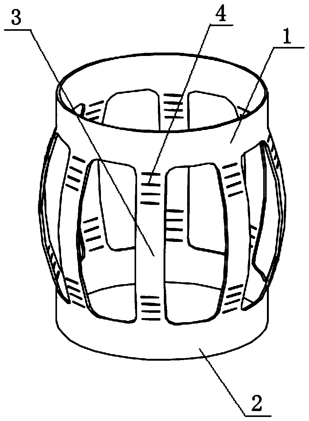
[0027] Such as figure 1 As shown, the centralizer of the present invention includes an upper end ring 1 and a lower end ring 2 with the same diameter; several working ribs 3 are fixedly connected between the upper end ring 1 and the lower end ring 2; the working ribs 3 surround the upper end ring 1 or the lower end ring The circumference of 2 is evenly distributed; the width of the working rib 3 is between 30-130 mm; and several stress relief grooves 4 are also included. The stress relief groove 4 is opened on the working rib 3 . The shape of the stress relief groove 4 is a horizontal straight line, a vertical straight line or an arc shape. The arc-shaped stress relief groove 4 located at the lower part of the working rib 3 is arranged in a herringbone shape. The radius range of the arc-shaped stress relief groove 4 is R20-80mm. The distance between the stress relief groove 4 and the edge of the working rib 3 on the same side is 10-20 mm. The length of a single stress reli...

Embodiment 2

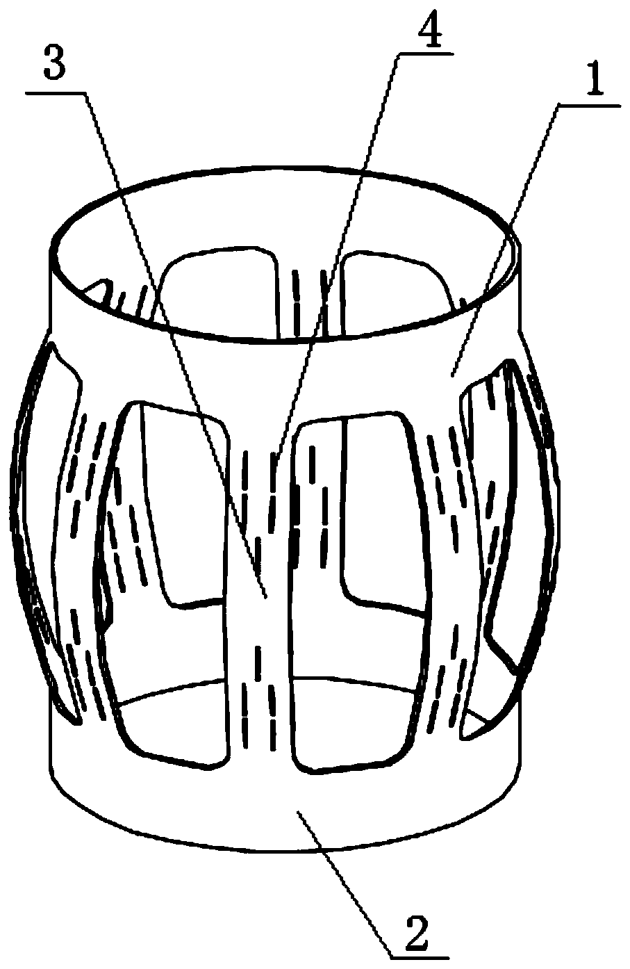
[0030] Such as figure 2 As shown, it is roughly the same as Embodiment 1, the only difference is that the shape of the stress relief groove 4 is a longitudinal linear shape; the stress relief groove 4 located at the lower part of the working rib 3 has several rows, the first row is one, and is located at the working rib 3. The longitudinal symmetry axis of the rib 3; below the second row, each row has two, and the two stress relief grooves 4 are symmetrically distributed, and the symmetry axis is collinear with the longitudinal symmetry axis of the working rib 3; two adjacent rows of stress relief grooves The longitudinal distance between 4 is consistent, which is 10-40mm; below the second row, the transverse distance between the two stress-relief grooves 4 in each row is 20-100mm.

Embodiment 3

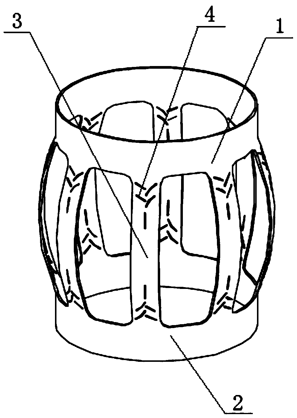
[0032] Such as image 3 As shown, it is roughly the same as that of Embodiment 1, the only difference is: specifically, there are several rows of stress relief grooves 4 located at the bottom of the working rib plate 3, and the first row is a longitudinal linear stress relief groove 4, which is located at the working rib The longitudinal axis of symmetry of the plate 3; below the second row, there are two in each row, and the two stress relief grooves 4 are distributed in a herringbone shape; the longitudinal distance between two adjacent rows of stress relief grooves 4 is at least 10 mm, and the maximum 40mm; below the second row, the lateral distance between the two stress relief grooves 4 in each row is at least 5mm and at most 30mm.


PUM


Abstract

The invention discloses a centralizer. The centralizer comprises an upper end ring and a lower end ring, wherein the diameters of the upper end ring and the lower end ring are consistent; a pluralityof working rib plates are fixedly connected between the upper end ring and the lower end ring; the working rib plates are evenly distributed around the circumference of the upper end ring or the lowerend ring; the width of the working rib plates is 30-130 mm; and the centralizer further comprises a plurality of stress relieving grooves. According to the centralizer, according to the actual usingdemands, the stress relieving grooves are formed in the working rib plates with different widths and the junctions of the rib plates and the end rings; and the stress relieving grooves provide stressdeforming spaces for body elastic materials when the rib plates are extremely extruded and deform, and thus structures of the body elastic materials are prevented from being destroyed or partially damaged.

Description

technical field [0001] The invention belongs to the technical field of oil drilling cementing equipment, and in particular relates to a centralizer. Background technique [0002] The centering degree of the casing in the wellbore is one of the decisive factors for the cementing quality of oil and gas wells, and the placement of the centralizer is the basis for whether the casing is centered or not. The centralizer is a component used to straighten the casing and ensure the concentricity of the casing in the wellbore. The performance of different types of centralizers has different effects on the casing run-in and final centering. The current centralizer is prone to problems that the working ribs are easily deformed permanently after being subjected to a large load, resulting in elastic casing centralizers. If the reset force is not enough, the centering of the casing in the wellbore will not be enough during cementing, which will reduce the quality of cementing. If the ecce...

Claims


Application Information

Patent Timeline
Patent Type & Authority Applications(China)
IPC IPC(8): E21B17/10
CPCE21B17/1042E21B17/1078
Inventor 王北兴陈龙龙
Owner SHAANXI NEWLAND IND
Why Eureka
Try Eureka