Straight-down-type slab backlight source

A backlight and direct-lit technology, applied in the field of backlight, can solve the problems of thick thickness, fluctuating with the wind, limited specifications, etc., and achieve the effect of meeting outdoor applications, improving luminous efficiency, and low manufacturing cost

Pending Publication Date: 2019-07-23
湖南凯星电子科技有限公司
View PDF4 Cites 0 Cited by
  • Summary
  • Abstract
  • Description
  • Claims
  • Application Information

AI Technical Summary

Problems solved by technology

There are also defects in the following aspects when using the direct-down backlight of this simple box structure to make light box display equipment: First, the box is surrounded by solid and opaque box walls, and there are serious problems after splicing into a light box with a large area of ​​light. dark frame
The second is that the thickness is too thick and the installation is inconvenient; although the method of installing a light diffusion plate on the opening surface can improve the uniformity of the emitted light and reduce the thickness of the cabinet, but the cabinet walls around the cabinet cannot achieve shadowless splicing The third is that due to the limited specifications of the finished material of the light-transmitting board or light-diffusing board (usually 1.22m×2.44m), the light box made into a larger size can only be directly covered with the light box cloth on the opening surface (called " Rab Light Box"), for the "Rab Light Box" that emits light in a large area, the light box cloth will fluctuate with the wind, which not only affects the appearance, but also is easy to be damaged and has a short service life; once the light box cloth is damaged, it will bring many inconveniences. safety factor
From the above, it can be seen that it is difficult to perform shadowless splicing of backlight in the prior art, resulting in the lack of large-area light-emitting backlight display devices on the market, especially large-area arc-shaped backlight display devices.

Method used


Image

  • Straight-down-type slab backlight source
  • Straight-down-type slab backlight source
  • Straight-down-type slab backlight source

Examples


Embodiment Construction

[0036] The technical solutions in the embodiments of the present invention are clearly and completely described below in conjunction with the drawings in the embodiments of the present invention.

[0037] The descriptions of the front side, the rear side, the inside, the outside, and the surroundings in this embodiment are based on the drawings and the positions in the implementation.

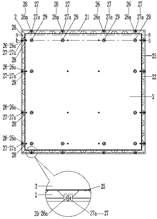
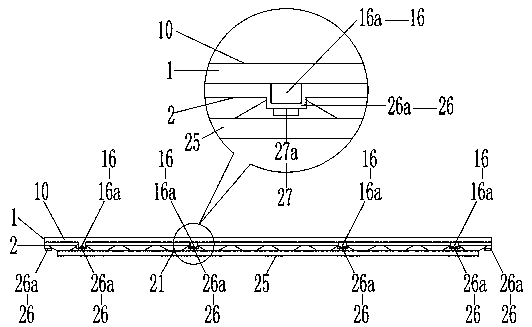
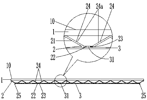
[0038] An embodiment of a direct-type flat panel backlight source in the present invention, such as Figure 1 to Figure 9 As shown, it consists of a plurality of conical cavities (21) that protrude backwards, are connected to each other, and are evenly distributed in an array, and the conical cavities (21) face backwards and the reflectors on the conical top surface 22. Lamp hole 23 and the conical reflector 2 that surrounds the guard edge 25 integrally formed on the reflector on the lamp hole 23 periphery on all reflectors; is installed on the conical reflector 2 front side diffusion plate 1; ...


PUM


Abstract

The invention relates to a straight-down-type slab backlight source. The straight-down-type slab backlight source comprises a conical reflecting cover, a light dispersion plate and a lamp plate, wherein the conical reflecting cover is integrally formed by multiple conical cavities which protrude backwards, and are connected mutually and uniformly distributed in an array, lamp holes formed in the conical top face part of the reflecting cover, and protection edges surrounding the peripheries of the lamp holes in the reflecting cover; the light dispersion plate is installed at the front side of the conical reflecting cover; the lamp plate is installed in the protection edges on the reflecting cover; light reflection layers coat the conical inner walls of the conical cavities; when the lamp plate is installed in the protection edges of the reflecting cover, a light emitting body of a light source penetrates through the lamp holes in the reflecting cover; light emitted by the light source is reflected and refracted on the light dispersion plate through the conical inner wall, and uniform light is emitted at the front side of the light dispersion plate after the light passes through thelight dispersion plate; through the overall and edge-free structure with the conical cavities which are uniformly distributed in an array, the light emitted by the light source is uniformly emitted onthe light dispersion plate, no dark edges exist, and display equipment capable of achieving large-area light emitting can be made through splicing.

Description

technical field [0001] The invention relates to the technical field of backlight sources, in particular to a direct-lit flat panel backlight source. Background technique [0002] The light diffusion module is the main part of the backlight. In real life, the application of backlight is extremely extensive, such as: TFT-LCD (liquid crystal display), light boxes, lighting and other special equipment. Among them, light boxes are the most widely used, such as: X-ray light-emitting devices, vision detectors, flat-panel lights, light curtains, floor lights, windows, containers, signs, architectural decorations, light box advertisements, traffic signs, guide signs, Light box signboards, light box advertisements, exhibitions, and military and transportation equipment (such as: aircraft carriers, submarines, ships, aircraft, high-speed rail, trains, automobiles) guide signs, etc. The uniformity of light is one of the important indicators of the backlight source. Different applicati...

Claims


Application Information

Patent Timeline
Patent Type & Authority Applications(China)
IPC IPC(8): F21S8/00F21V3/02F21V7/04F21V13/04F21V7/28F21V17/12G02F1/13357
CPCF21S8/00F21V3/02F21V7/041F21V13/04F21V7/28F21V17/12G02F1/133605G02F1/133606G02F1/133607
Inventor 罗言超姚淑英
Owner 湖南凯星电子科技有限公司
Why Eureka
Try Eureka