Ceramic glaze drying device

A drying device and a technology for ceramic glaze, applied in the field of ceramic machinery, can solve the problems of difficult dispersion, unsatisfactory drying effect, and easy accumulation of ceramic glaze, so as to achieve rapid drying, increase volatilization, and avoid accumulation and agglomeration. Effect

Active Publication Date: 2019-07-23
GUANGDONG VOCATIONAL & TECHNICAL COLLEGE
View PDF6 Cites 9 Cited by
  • Summary
  • Abstract
  • Description
  • Claims
  • Application Information

AI Technical Summary

Benefits of technology

This technology improves how well it dries out ceramics during production without getting stuck or damaged due to excessive moisture content inside them. It uses an oscillating motion instead of rotational movement for better distribution over multiple parts of the process. A pump pulls off any condensations on top before sending this gas back into the system again after being treated.

Problems solved by technology

This patented technology describes how it works for different types of materials like pearls or tiles that have been used during firing process. However, there may also exist some cases where these objects were difficult to remove from their original shape due to sticking together when they had just started burning them downward onto another object placed next up along its pathway. To address this problem, certain devices use special tools such as brushers to help break off any stuck material beforehand. These techniques aimed at improving efficiency while maintaining consistently high quality results over time.

Method used


Image

  • Ceramic glaze drying device
  • Ceramic glaze drying device
  • Ceramic glaze drying device

Examples


Embodiment 1

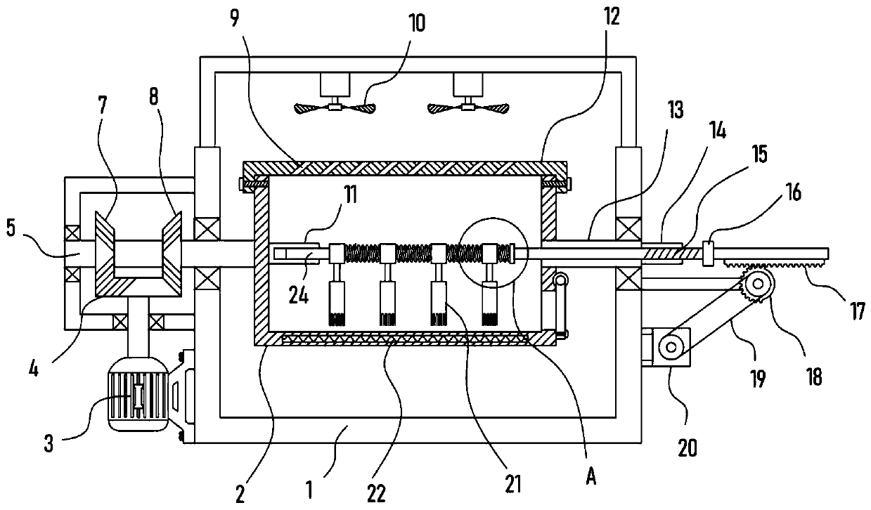
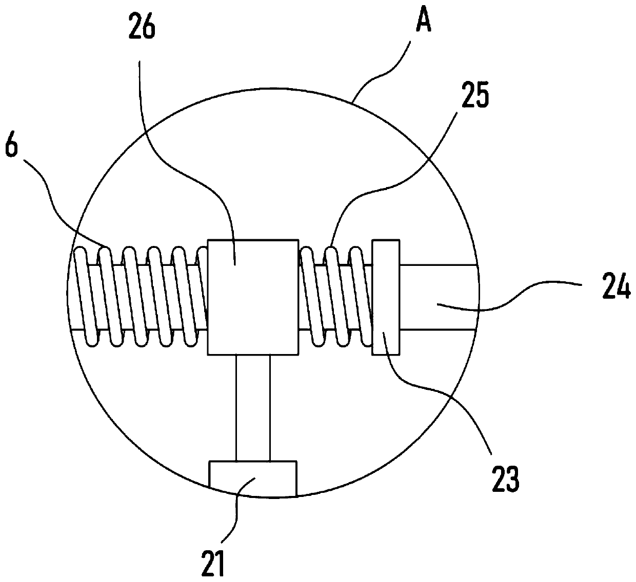
[0022] see Figure 1-3 , a ceramic glaze drying device, comprising a support frame 1, a drying cylinder 2 is installed on the support frame 1, a heater 22 is embedded and fixed at the bottom of the drying cylinder 2, and the two sides of the drying cylinder 2 are respectively the same The axis is fixed with the drive shaft 5 pivotally connected with the support frame 1 and the limit sleeve 13. The drive shaft 5 is connected with an intermittent mechanism driven by the motor I3. The rotating shaft 24 is connected with a dispersion mechanism on the rotating shaft 24, and a cover plate 12 is detachably installed on the top of the drying cylinder 2.

[0023] The provided drying cylinder 2 is used to hold the ceramic glaze to be dried, and the cover plate 12 is used to perform dust-proof treatment on the drying cylinder 2 to prevent dust and sundries from falling into the drying cylinder 2 . The heater 22 heats the drying cylinder 2 to realize the temperature rise inside the dryin...

Embodiment 2

[0028] In order to further improve the water distribution efficiency of the ceramic glaze and improve the drying effect, on the basis of Embodiment 1, the drive mechanism includes a toothed rack 17 and an incomplete gear 18 for meshing transmission. The rack 17 is fixed with a connecting block 16 and a rotating shaft 24. Pivoted on the connecting block 16, the rotating shaft 24 is sleeved with a threaded pipe 14 fixed outside the support frame 1, and the surface of the rotating shaft 24 is tapped with an external thread 15 adapted to the internal thread of the threaded pipe 14. The driving mechanism also includes a motor II20 , the output shaft of the motor II20 is rotationally connected with the incomplete gear 18 through the pulley mechanism 19 .

[0029] The incomplete gear 18 drives the rotating shaft 24 to produce a lateral displacement through the rack 17 meshing with it, and the external thread 15 on the rotating shaft 24 and the internal thread of the threaded pipe 14 a...


PUM


Abstract

The invention discloses a ceramic glaze drying device, and relates to the technical field of ceramics. A supporting frame is included and rotationally provided with a drying barrel. A heater is fixedto the bottom of the drying barrel in an embedded manner. A driving shaft and a limiting casing pipe which are in pin joint to the supporting frame are fixed to the two sides of the drying barrel withthe same axis correspondingly. The driving shaft is in transmission connection with an intermittent mechanism driven by a motor I. A rotation shaft is in transmission connection with a dispersing mechanism, and the top of the drying barrel is detachably provided with a cover plate. Through swinging of the arranged drying barrel, swinging of inner ceramic glaze is promoted, and the effect of sufficient heating of the ceramic glaze through the heater is promoted. The arranged dispersing mechanism can rotate and can also transversely reciprocate, the ceramic glaze can be dispersed, stacking andcaking are avoided, and water vapor volatilization can be effectively improved; and an arranged axial-flow fan vertically upwards guides air, water vapor can be rapidly discharged out of the drying barrel, and the effect of rapid drying of the ceramic glaze is achieved.

Description


Claims


Application Information

Patent Timeline
Owner GUANGDONG VOCATIONAL & TECHNICAL COLLEGE
Why Eureka
Try Eureka