
High temperature strain test device based on F-P optical fiber sensor and mounting method of high temperature strain test device

An optical fiber sensor and testing device technology, applied in the testing field, can solve the problem of large measurement error of the test piece

Inactive Publication Date: 2019-07-23
NORTHWESTERN POLYTECHNICAL UNIV
View PDF6 Cites 6 Cited by
  • Summary
  • Abstract
  • Description
  • Claims
  • Application Information

AI Technical Summary

Problems solved by technology

[0004] In the prior art, the cavity length of the F-P optical fiber sensor in the strain test device is easily affected by high temperature, which leads to a large measurement error of the strain of the test piece

Method used


Image

  • High temperature strain test device based on F-P optical fiber sensor and mounting method of high temperature strain test device
  • High temperature strain test device based on F-P optical fiber sensor and mounting method of high temperature strain test device
  • High temperature strain test device based on F-P optical fiber sensor and mounting method of high temperature strain test device

Examples


Embodiment Construction

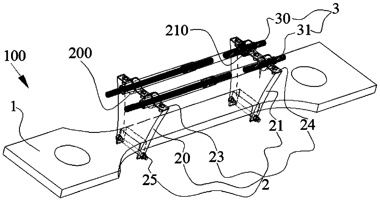
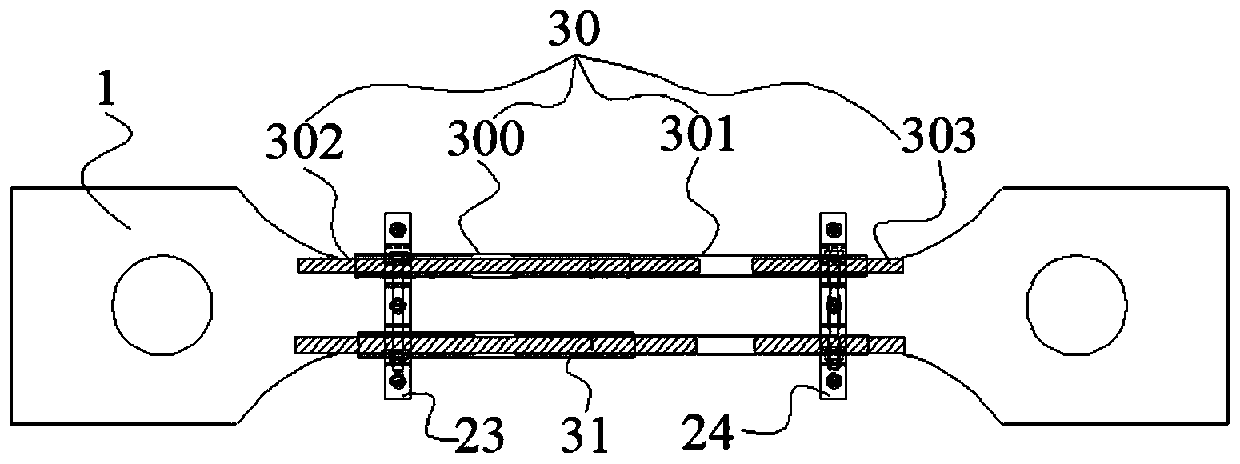
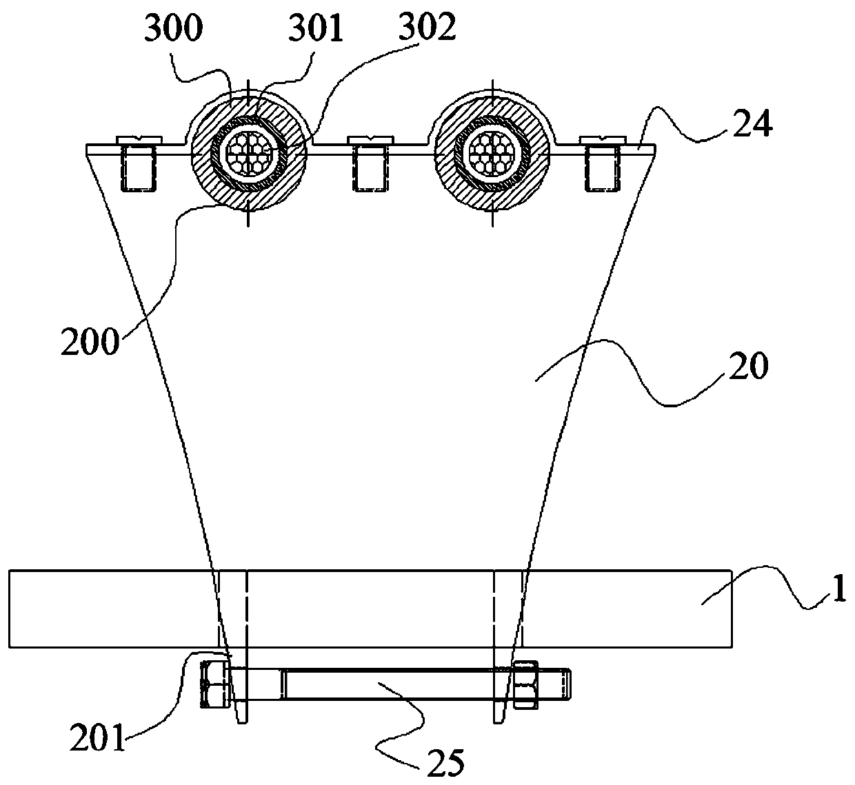
[0038] Example embodiments will now be described more fully with reference to the accompanying drawings. Example embodiments may, however, be embodied in many forms and should not be construed as limited to the embodiments set forth herein; rather, these embodiments are provided so that this disclosure will be thorough and complete, and will fully convey the concept of example embodiments to those skilled in the art. The same reference numerals in the drawings denote the same or similar structures, and thus their detailed descriptions will be omitted.

[0039] Although relative terms such as "upper" and "lower" are used in this specification to describe the relative relationship of one component of an icon to another component, these terms are used in this specification only for convenience, for example, according to the description in the accompanying drawings directions for the example described above. It will be appreciated that if the illustrated device is turned over so...


PUM


Abstract

The invention relates to the technical field of testing, in particular to a high temperature strain test device based on an F-P optical fiber sensor and a mounting method of the high temperature strain test device. The high temperature strain test device is used for strain test of a to-be-tested test piece. The high temperature strain test device comprises a support assembly and a sensor assembly,wherein the support assembly comprises a first support and a second support, the first support and the second support are oppositely arranged, and the first support and the second support are used for being connected with the to-be-tested test piece; and the sensor assembly comprises a first F-P optical fiber sensor and a second F-P optical fiber sensor, the two ends of the first F-P optical fiber sensor are correspondingly and fixedly connected with the first support and the second support, the second F-P optical fiber sensor is fixedly connected with one of the first support and the secondsupport, and is relatively independent relative to the other one of the first support and the second support. The strain test error of the to-be-tested test piece in the high temperature can be reduced through the high temperature strain test device.

Description

technical field [0001] The disclosure relates to the technical field of testing, in particular to a high-temperature strain testing device based on an F-P optical fiber sensor and an installation method thereof. Background technique [0002] Optical fiber sensor is a sensor that can convert the state of the measured object into a measurable optical signal. Compared with traditional strain sensors, optical fiber sensor has the characteristics of small size, light weight and high sensitivity, so it is widely used in rocket propulsion Systems, key parts of spacecraft, and health warning of building structures. [0003] Among them, the F-P (Fabry-Perot, Fabry-Perot) optical fiber sensor has an F-P cavity, which is usually formed by placing the end faces of two optical fibers in parallel. Multiple reflections. During the use of the F-P fiber optic sensor, the interference phenomenon of multiple beams can be used to measure the change of the cavity length, so as to realize the a...

Claims


Application Information

Patent Timeline
IPC IPC(8): G01D5/353G01B11/16
CPCG01B11/161G01D5/35312
Inventor 温志勋岳珠峰李飞吴子燕吴家骥
Owner NORTHWESTERN POLYTECHNICAL UNIV
Learn More