Flat backlight

A technology of backlight source and flat panel, applied in the field of backlight source, can solve the problems of thick thickness, opaqueness, limited specifications, etc., to achieve the effect of improving luminous efficiency, satisfying outdoor applications, and low manufacturing cost

Inactive Publication Date: 2019-07-23
湖南凯星电子科技有限公司
View PDF0 Cites 0 Cited by
  • Summary
  • Abstract
  • Description
  • Claims
  • Application Information

AI Technical Summary

Problems solved by technology

There are also defects in the following aspects when using the direct-down backlight of this simple box structure to make light box display equipment: First, the box is surrounded by solid and opaque box walls, and there are serious problems after splicing into a light box with a large area of ​​light. dark frame
The second is that the thickness is too thick and the installation is inconvenient; although the method of installing a light diffusion plate on the opening surface can improve the uniformity of the emitted light and reduce the thickness of the cabinet, but the cabinet walls around the cabinet cannot achieve shadowless splicing The third is that due to the limited specifications of the finished material of

Method used


Image

  • Flat backlight
  • Flat backlight
  • Flat backlight

Examples


Embodiment Construction

[0037] The technical solutions in the embodiments of the present invention are clearly and completely described below in conjunction with the drawings in the embodiments of the present invention.

[0038] The descriptions of the front side, the rear side, the inside, the outside, and the surroundings in this embodiment are based on the drawings and the positions in the implementation.

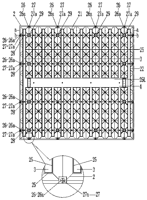
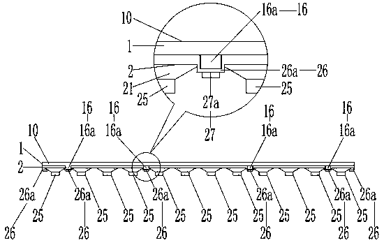
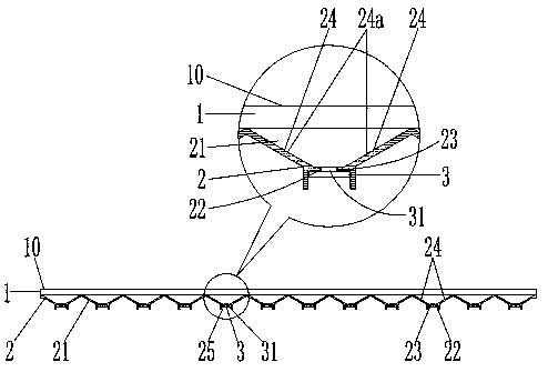
[0039] A flat backlight embodiment of the present invention, such as Figure 1 to Figure 9 As shown, the backlight includes a diffuser plate 1, a conical reflector 2, and a light bar 3, and the front side of the light bar 3 is provided with a light source 31 arranged in a line; Interconnected, evenly distributed in an array, the conical cavity 21 facing the rear of the conical top surface 22 and the lamp hole 23 on the reflector at the conical top surface 22 and the conical cavity surrounding each row or column The light groove 25 on the reflector of top surface 22 is integrally formed; a lay...


PUM


Abstract

The invention relates to a flat backlight, which comprises light-scattering plates, a conical reflector and a light bar. The conical reflector of the flat backlight is integrally formed by a pluralityof conical cavities, light holes and light troughs, wherein the multiple conical cavities protrude backwards, are connected to one another and uniformly distributed according to an array, and have backward conical top faces, the light holes are formed in reflectors at the conical top face parts, and the light troughs surround the reflectors of each row or each column of the conical top faces; theconical inner walls of the conical cavities are coated with reflective layers, a connection mechanism on a plurality of light-scattering plates is arranged on the positions, near the edge parts, around the rear sides of the light-scattering plates, and a connection mechanism on the reflectors is arranged on the positions, near the edge parts, around the conical reflectors; and light strips are mounted in the light troughs 25 on the reflectors, light of light sources on the light strips penetrate through the light holes in the reflectors, and the light-scattering plates are installed on the front sides of the conical reflectors and fixed through the connecting mechanism on the light-scattering plates and the connecting mechanism on the reflectors. According to the technical scheme, the light emitted by the light sources shine evenly on the light-scattering plates without dark edges, after being spliced together, obvious edge lines and dark fringes can also be avoided, and display equipment with large-area luminescence can be made by splicing.

Description

technical field [0001] The invention relates to the technical field of backlight sources, in particular to a flat panel backlight source. Background technique [0002] The light diffusion module is the main part of the backlight. In real life, the application of backlight is extremely extensive, such as: TFT-LCD (liquid crystal display), light boxes, lighting and other special equipment. Among them, light boxes are the most widely used, such as: X-ray light-emitting devices, vision detectors, flat-panel lights, light curtains, floor lights, windows, containers, signs, architectural decorations, light box advertisements, traffic signs, guide signs, Light box signboards, light box advertisements, exhibitions, and military and transportation equipment (such as: aircraft carriers, submarines, ships, aircraft, high-speed rail, trains, automobiles) guide signs, etc. The uniformity of light is one of the important indicators of the backlight source. Different applications have di...

Claims


Application Information

Patent Timeline
IPC IPC(8): G02F1/13357
CPCG02F1/133603G02F1/133605G02F1/133606G02F1/133608
Inventor 罗言超姚淑英
Owner 湖南凯星电子科技有限公司
Why Eureka
Try Eureka