Supercharge Your Innovation With Domain-Expert AI Agents!

Automatic holding type gas-liquid chuck

A gas-hydraulic, automatic technology, applied in the direction of the chuck, etc., can solve the problem of unbalanced clamped workpieces, and achieve the effects of high precision fit, improved integrity, and precise travel

Pending Publication Date: 2019-07-26
刘明亮
View PDF0 Cites 0 Cited by
  • Summary
  • Abstract
  • Description
  • Claims
  • Application Information

AI Technical Summary

Problems solved by technology

[0005] In view of this, the purpose of the present invention is to overcome the deficiencies of the prior art, and provide an automatic clamping type air-liquid chuck to solve the problem that the jaws of the chuck in the prior art are easily caused by the process of clamping the workpiece due to the independent setting. Unbalanced technical issues

Method used


Image

  • Automatic holding type gas-liquid chuck
  • Automatic holding type gas-liquid chuck
  • Automatic holding type gas-liquid chuck

Examples


Embodiment 1

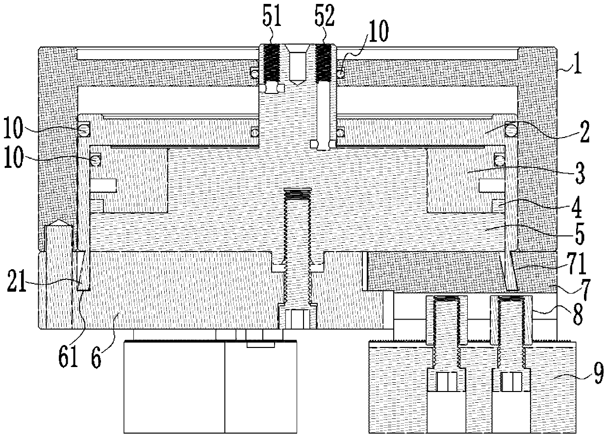
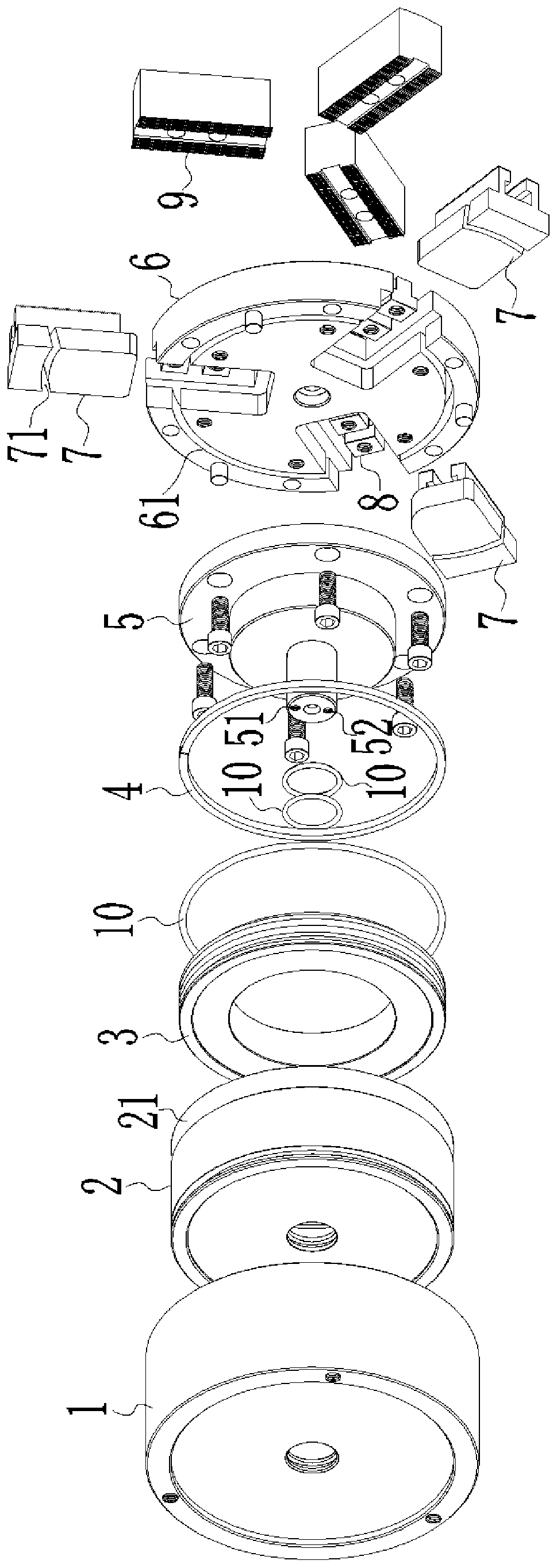
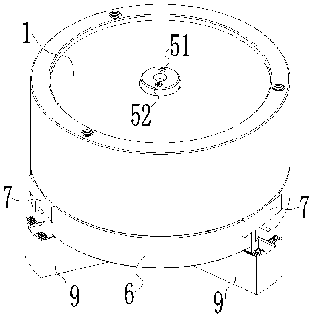
[0031] A self-clamping gas-liquid chuck, such as Figure 1 to Figure 4 As shown, it includes a housing 1 , a piston cylinder 2 , a core seat 5 , a base 6 , a slider 7 and a claw 9 . Wherein, the piston cylinder 2 is sleeved in the housing 1 and can slide freely in the housing 1 , and the centers of the housing 1 and the piston cylinder 2 are both provided with a central hole. In the center of the core base 5, there is a central column that runs through the center hole of the housing 1 and the piston cylinder 2. The a medium hole 51 and the b medium hole 52 are arranged on the central column. The a medium hole 51 communicates between the housing 1 and the piston cylinder 2. , B medium hole 52 communicates between the piston cylinder 2 and the core seat 5 . The bottom of the base 6 is connected with claws 9 for clamping workpieces.

[0032] Such as Figure 1 to Figure 4 As shown, the bottom of the piston cylinder 2 has a complete circular wedge-shaped mouth 21, and the openin...

Embodiment 2

[0036] Most of the technical solutions of this embodiment are the same as those of the above-mentioned embodiments, but the following configuration structures are adopted in particular:

[0037] Such as Figure 5 As shown, the bottom of the piston cylinder 2 has a complete circular wedge-shaped mouth 21, and the opening direction of the wedge-shaped mouth 21 is toward the inner side of the piston cylinder 2, forming a reverse trumpet-shaped structure. When the piston cylinder 2 is pushed upward, the wedge-shaped mouth 21 gradually extends out of the base 6, and the claw 9 clamps the workpiece to make the wedge-shaped mouth 21 move inwardly. The outer sidewall of the limiting groove 61 is tightened by the outward displacement.

[0038] The bottom of the piston cylinder 2 of the present invention is a complete circular wedge-shaped opening 21. When the three sets of claws 9 clamp the workpiece under force, the three sets of claws 9 drive the slider 7 so that the wedge-shaped op...

Embodiment 3

[0040] As preferably, in order to realize the present invention better, optimize further on the basis of above-mentioned embodiment, especially adopt following setting structure:

[0041] like Figure 1 to Figure 4 As shown, the core seat 5 has a stepped structure, and the core seat 5 and the piston cylinder 2 form a cavity at the step position, and the elastic member 3 is arranged in the cavity. The material of the elastic member 3 can be nylon, rubber, silica gel, beef tendon or hollow metal and other materials with elastic expansion and contraction.

[0042] When the medium (gas or liquid) enters between the casing 1 and the piston cylinder 2 from the a medium hole 51, or enters between the piston cylinder 2 and the core seat 5 from the b medium hole 52, the piston cylinder 2 moves in the casing 1 to The driving claw 9 clamps the workpiece. In this process, due to the existence of the elastic member 3, the outer wall of the piston cylinder 2 is tightly attached to the inner...


PUM

PropertyMeasurementUnit
Diameteraaaaaaaaaa

Abstract

The invention discloses an automatic holding type gas-liquid chuck, relates to the technical field of chuck devices for machine tools and solves the technical problem of unbalance easily caused by independent arrangement of a clamping claw in a chuck in the workpiece clamping process in the prior art. The automatic holding type gas-liquid chuck comprises an outer shell, a piston cylinder, a core base and a base, wherein a wedge-shaped opening in a whole circular ring shape is arranged at the bottom of the piston cylinder, the base is provided with a a limiting groove and sliding blocks, and the limiting groove and wedge-shaped grooves form a whole circular ring groove structure corresponding to the wedge-shaped opening. The bottom of the piston cylinder is the wedge-shaped opening in the whole circular ring shape, after clamping jaws clamp a workpiece and are stressed, the clamping jaws drive the sliding blocks so that the wedge-shaped opening at the wedge-shaped grooves can produce small deformation, the bottom of the piston cylinder is deformed into a non-circular shape after multipoint stress, the piston cylinder is directly held on the base and the sliding blocks, the integrityamong the clamping jaws is improved, the center of holding resultant force coincides with the center of the chuck, and thus the chuck reaches a stress balance state.

Description

technical field [0001] The invention relates to the technical field of chuck devices for machine tools, in particular to an automatic clamping type air-liquid chuck. Background technique [0002] The chuck is a mechanical device used to clamp the workpiece on the machine tool. It is a machine tool accessory that uses the radial movement of the movable jaws evenly distributed on the chuck to clamp and position the workpiece. The chuck is generally composed of three parts: the chuck body, the movable jaws and the jaw driving mechanism. The chuck is usually installed on lathes, cylindrical grinders and internal grinders, and can also be used in conjunction with various indexing devices for milling machines. and drill press. [0003] Chucks in the present technology, especially pneumatic chucks or hydraulic chucks usually use claws to hold the workpiece to be clamped, but these claws are set independently of each other and have no connection with each other. If it is necessary...

Claims


Application Information

Patent Timeline
IPC IPC(8): B23B31/30B23B31/10
CPCB23B31/30B23B31/10Y02P70/10
Inventor 刘明亮
Owner 刘明亮
Features
  • R&D
  • Intellectual Property
  • Life Sciences
  • Materials
  • Tech Scout
  • Unparalleled Data Quality
  • Higher Quality Content
  • 60% Fewer Hallucinations
Learn More