Sample rotating rack and Raman spectroscopy detector

A technology of Raman spectroscopy and a rotating frame, which is applied in the field of biological science research and application, can solve the problems of numerous operation steps, high price, and bulky volume, and achieve the effects of accurate positioning, time saving, and improved detection efficiency

Inactive Publication Date: 2019-07-26
ACADEMY OF MILITARY MEDICAL SCI
View PDF15 Cites 1 Cited by
  • Summary
  • Abstract
  • Description
  • Claims
  • Application Information

AI Technical Summary

Problems solved by technology

[0006] The object of the present invention is to provide a sample rotating frame and a Raman spectrometer to solve the problems of the Raman spectrometer in the prior art, such as bulky size, complex structure, high price, numerous operation steps, and low detection efficiency.

Method used


Image

  • Sample rotating rack and Raman spectroscopy detector
  • Sample rotating rack and Raman spectroscopy detector
  • Sample rotating rack and Raman spectroscopy detector

Examples


Embodiment 1

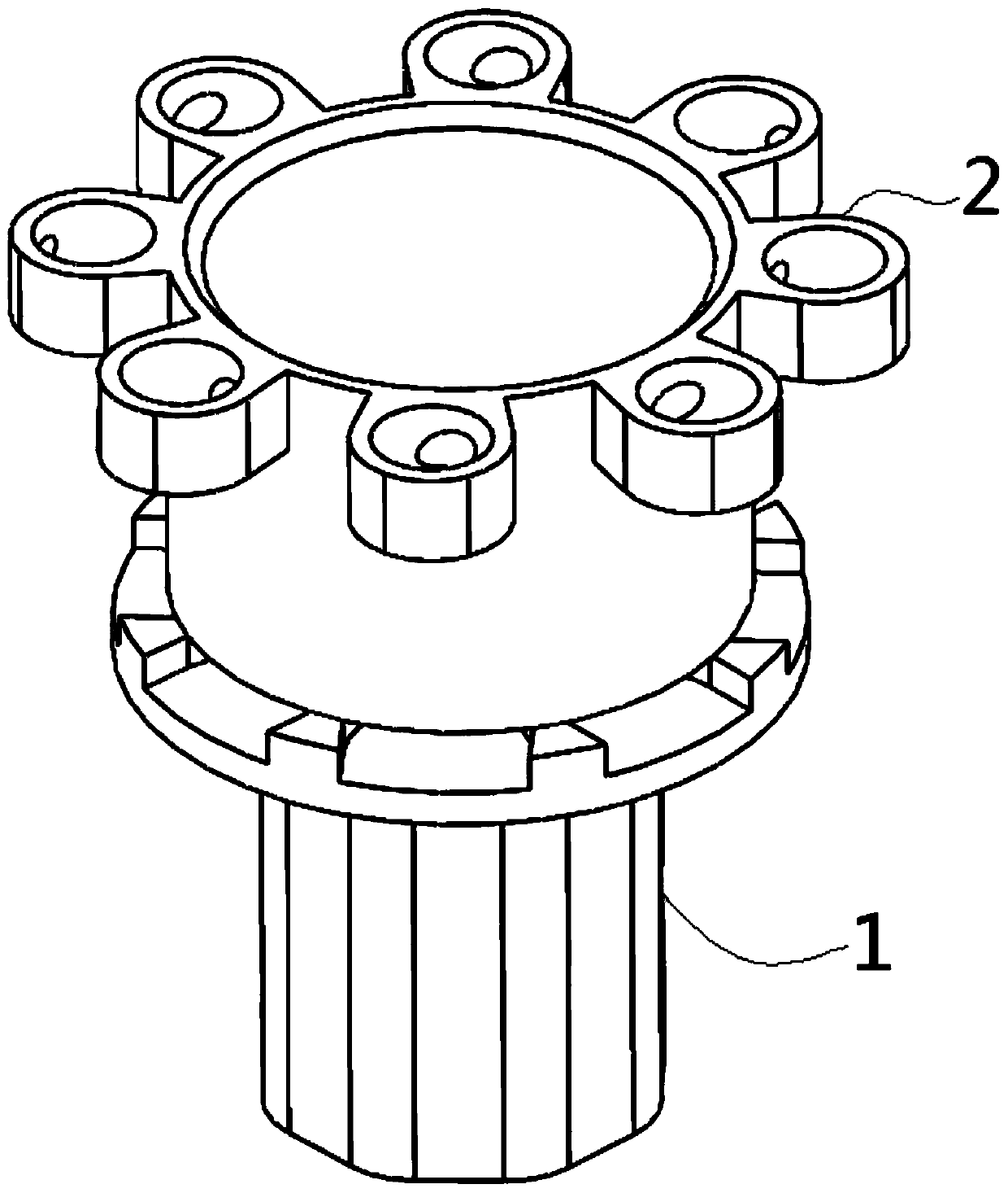
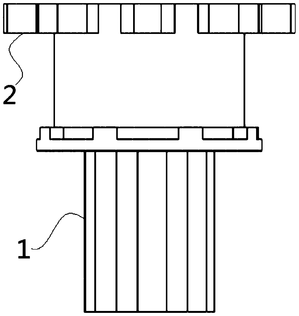
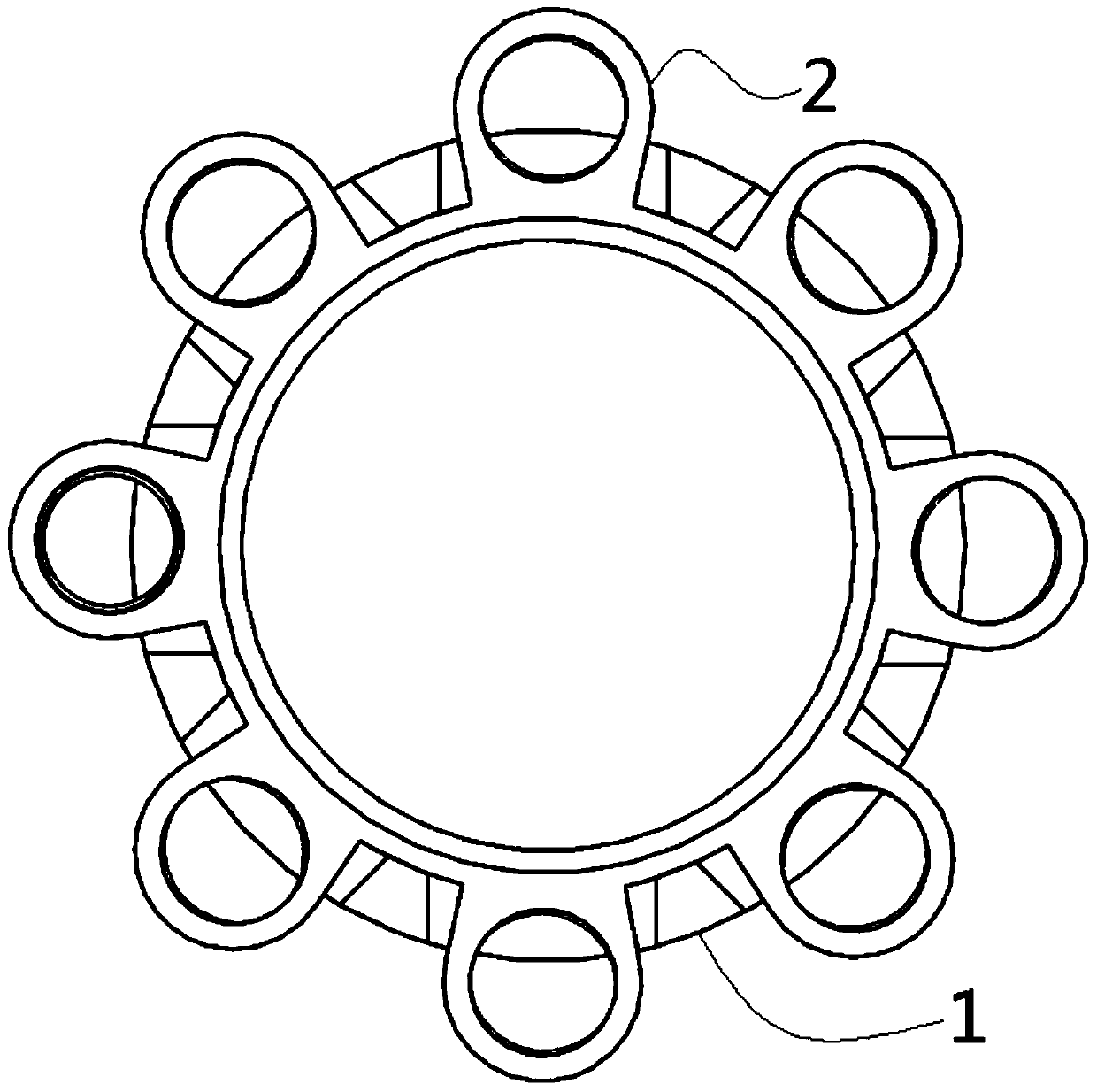
[0061] This embodiment provides a sample rotating rack, wherein: figure 1 A perspective view of the sample rotating rack provided in Embodiment 1 of the present invention; figure 2 The front view of the sample rotating rack provided by Embodiment 1 of the present invention; image 3 A top view of the sample rotation rack provided in Embodiment 1 of the present invention. Such as Figure 1~3 As shown, the sample rotating rack includes a rotating body 1 and a plurality of sample carriers arranged thereon; the plurality of sample carriers are distributed around the circumference of the rotating body 1 and can be irradiated by light located at the periphery of the rotating body 1 .

[0062] Such as Figure 1~3 As shown, wherein the sample carrier is a ring sleeve 2, and a plurality of ring sleeves 2 are arranged around the rotating body 1 in a circumferential direction, and are used for inserting and fixing test tubes. In this structure, the test tube can directly load the so...

Embodiment 2

[0064] This embodiment provides a sample rotating rack, wherein: Figure 4 A perspective view of the sample rotating frame provided for the second embodiment of the present invention; Figure 5 The front view of the sample rotating frame provided for the second embodiment of the present invention; Figure 6 A top view of the sample rotation rack provided by Embodiment 2 of the present invention. Such as Figure 4~6 As shown, the sample rotating rack includes a rotating body 1 and a plurality of sample carriers arranged thereon; the plurality of sample carriers are distributed around the circumference of the rotating body 1 and can be irradiated by light located at the periphery of the rotating body 1 .

[0065] Such as Figure 4~6 As shown, wherein the rotating body 1 is cylindrical, the sample carrier is a lumen 3 arranged on the side wall of the rotating body 1, and a plurality of sample carriers are arranged around the rotating body 1; The axial directions are parallel;...

Embodiment 3

[0067] This embodiment provides a sample rotating rack, wherein: Figure 7 A perspective view of the sample rotating rack provided in Embodiment 3 of the present invention; Figure 8 The front view of the sample rotating frame provided for the third embodiment of the present invention; Figure 9 A top view of the sample rotation rack provided in Embodiment 3 of the present invention. Such as Figure 7-9 As shown, the sample rotating rack includes a rotating body 1 and a plurality of sample carriers arranged thereon; the plurality of sample carriers are distributed around the circumference of the rotating body 1 and can be irradiated by light located at the periphery of the rotating body 1 .

[0068] Such as Figure 7-9 As shown, wherein the rotating body 1 is cylindrical, the sample carrier is a lumen 3 arranged on the side wall of the rotating body 1, and a plurality of sample carriers are arranged around the rotating body 1; The axial directions are parallel; any lumen 3...


PUM


Abstract

The invention provides a sample rotating rack and a Raman spectroscopy detector. The sample rotatingrackcomprises a rotating body and a plurality of sample carriers arranged on the rotating body; andthe sample carriers are distributed around the circumference of the rotating body and are illuminable by light rays located around the periphery of the rotating body. The sample rotating rack is provided with as many sample carriers as possible in a space as small as possible, and optical irradiation of a plurality of samples can be quickly conducted by rotating the rotating body;the Raman spectroscopy detector comprises a laser device, a spectrum analyzer, a Raman probe, a rotating table, and the sample rotating rack; the sample rotating rack is arranged on the rotating table, the Raman probeis arranged on the periphery of the sample rotating rack, and the Raman probe is electrically connected with the laser device and the spectrum analyzercorrespondingly; and the laser device is used for emitting excitation light through the Raman probe, and the Raman probe can receive Raman scattering spectra and return to the spectrum analyzer. Raman spectroscopy detector can rapidly perform optical analysis detectionon multiple samples by using the laser device, the spectrum analyzer, the rotating table, and the sample rotating rack.

Description

technical field [0001] The invention relates to the technical field of biological science research and application, in particular to a sample rotating rack and a Raman spectrum detector. Background technique [0002] Raman scattering, also known as the Raman effect, refers to the scattering of the frequency change caused by the interaction between the incident light and the molecular motion of the medium. produced. [0003] The frequency difference between the scattered light and the incident light is called the Raman shift, and the Raman shift has nothing to do with the frequency of the incident light, it is only related to the structure of the scattering molecule itself. The size of the Raman shift depends on the change of the molecular vibration energy level, and the molecular vibrations of different chemical bonds or the inherent characteristics of the group, so the corresponding Raman shifts are also different. This is the basis that Raman spectroscopy can be used as ...

Claims


Application Information

Patent Timeline
Patent Type & Authority Applications(China)
IPC IPC(8): G01N21/65G01N21/01G01N33/558
CPCG01N21/65G01N21/01G01N33/558G01N21/253G01J3/0291G01J3/44G01N35/04G01N2035/0441G01N2201/021G01N2201/06113
Inventor 王升启肖瑞荣振
Owner ACADEMY OF MILITARY MEDICAL SCI
Why Eureka
Try Eureka