Fault pole selection method utilizing decaying aperiodic components

A non-periodic and component technology, applied in the field of DC transmission line fault pole selection, can solve the problems of identification interference, insufficient discrimination, etc., and achieve the effect of simple algorithm, reliable pole selection, and simple logic structure

Inactive Publication Date: 2019-07-26
KUNMING UNIV OF SCI & TECH
View PDF7 Cites 2 Cited by
  • Summary
  • Abstract
  • Description
  • Claims
  • Application Information

AI Technical Summary

Problems solved by technology

In the past, our pole selection was based on the simulation analysis of the coupling characteristics of the UHV DC bipolar transmission line and its influencing factors, and then proposed the method of using t

Method used


Image

  • Fault pole selection method utilizing decaying aperiodic components
  • Fault pole selection method utilizing decaying aperiodic components
  • Fault pole selection method utilizing decaying aperiodic components

Examples


Embodiment 1

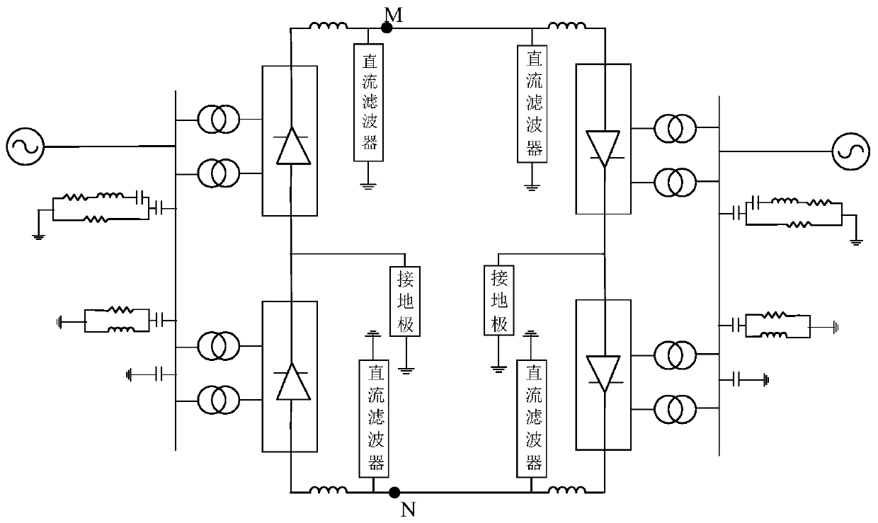
[0031] Embodiment 1: A certain 1100kV DC transmission line simulation model is as follows figure 1 shown. Its line parameters are as follows: The total length of the direct current transmission line is 3300km. Fault location: The positive line is 100km away from the M terminal. The sampling frequency is 10kHz.

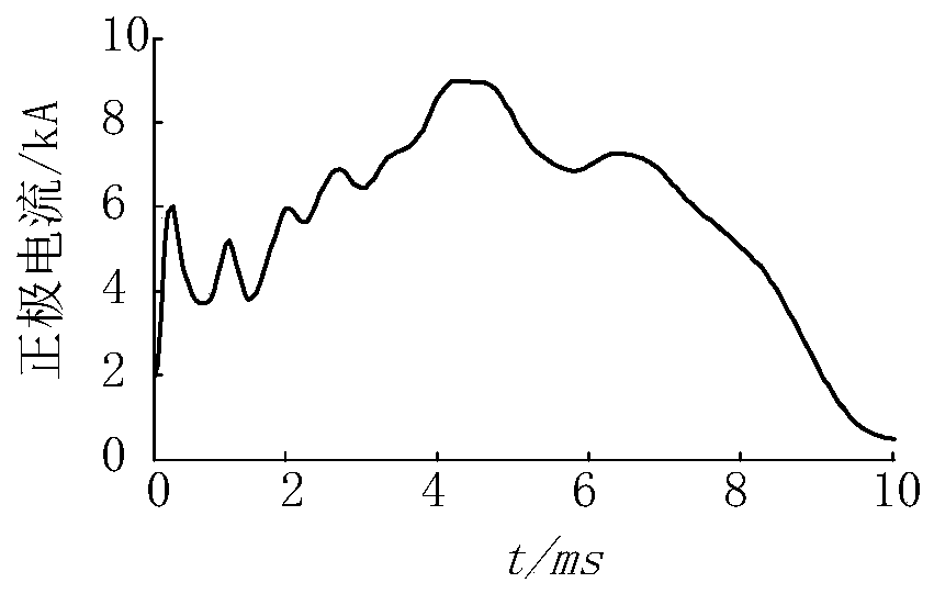
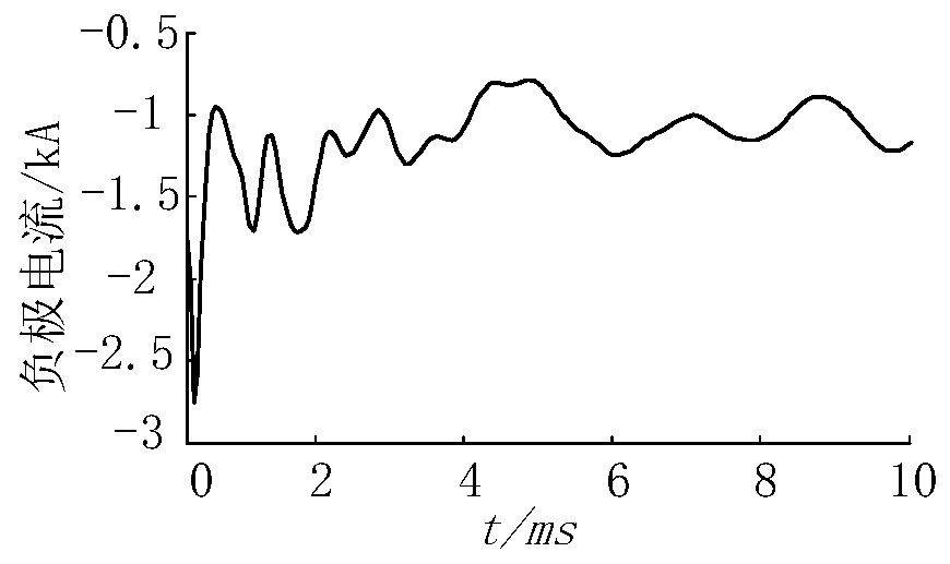
[0032] (1) Obtain the fault current waveform and data at the measuring end according to the first step in the manual, the waveform is as follows figure 2 with image 3 shown.

[0033] (2) According to the second to third steps in the manual, the attenuated DC component can be obtained, and the waveform is as follows Figure 4 with Figure 5 shown.

[0034] (3) According to the calculation formula of the attenuated DC component energy in the fourth step of the manual, the energy E of the attenuated non-periodic component of the current at the measurement terminal of the bipolar line is obtained + and E - ,As shown in Table 1.

[0035] (4) According to the fif...

Embodiment 2

[0038] Embodiment 2: A certain 1100kV DC transmission line simulation model is as follows figure 1 shown. Its line parameters are as follows: The total length of the direct current transmission line is 3300km. Fault location: The fault occurred on the negative pole line 750km away from the N terminal. The sampling frequency is 10kHz.

[0039] (1) Obtain the fault current waveform and data at the measuring end according to the first step in the manual, the waveform is as follows Image 6 with Figure 7 shown.

[0040] (2) According to the second to third steps in the manual, the attenuated DC component can be obtained, such as the waveform Figure 8 with Figure 9 shown.

[0041] (3) According to the calculation formula of the attenuated DC component energy in the fourth step of the manual, the energy E of the attenuated non-periodic component of the current at the measurement terminal of the bipolar line is obtained + and E - ,As shown in table 2.

[0042] (4) Accord...


PUM


Abstract

The invention belongs to the field of fault pole selection for a direct current power transmission line, and relates to a fault pole selection method utilizing the decaying aperiodic components. The method comprises the following steps: reading measuring end currents of a positive line and a negative line acquired by high-speed acquisition devices at measuring ends; carrying out detection and calibration on the acquired currents through wavelet decomposition, so that the decaying aperiodic components are obtained, and energies of the decaying aperiodic components are further calculated; and comparing the energies of the decaying aperiodic components of the measuring end currents of the positive line and the negative line, determining the pole with a larger decaying aperiodic component energy as a fault pole, and determining that both the positive line and the negative line are faulted if the energies of the decaying aperiodic components calculated for the positive pole and the negativepole are identical. The method provided by the invention has the advantages that the decaying aperiodic components within a short time window after the fault are extracted, and whether the decaying aperiodic components of the positive line and the negative line are obviously different or not is judged, so that reliable pole selection can be facilitated.

Description

technical field [0001] The invention relates to a fault pole selection method using attenuation aperiodic component, which belongs to the field of fault pole selection of direct current transmission lines. Background technique [0002] HVDC transmission plays an important role in long-distance and high-power transmission due to its large transmission capacity, low line cost, and good control performance. Due to the long transmission distance of the HVDC transmission system, the transient harmonic content after the fault is rich, which makes the coupling effect between the poles of the transmission line significant. Inductive electric quantity is generated in the healthy pole circuit, which causes the protection malfunction of the healthy pole line, so it is particularly important to select the pole reliably. In the past, our pole selection was based on the simulation analysis of the coupling characteristics of the UHV DC bipolar transmission line and its influencing factors...

Claims


Application Information

Patent Timeline
IPC IPC(8): G01R31/08
CPCG01R31/086G01R31/088
Inventor 束洪春王璇张雪飞田鑫萃
Owner KUNMING UNIV OF SCI & TECH
Why Eureka
Try Eureka