
High-voltage direct-current transmission line protection method and device based on single-ended transient energy

A transient energy, high-voltage DC technology, applied in circuit devices, emergency protection circuit devices, components of emergency protection devices, etc., can solve the problems of long protection action time, poor ability to withstand transition resistance, etc., and achieve obvious fault characteristics. , The effect of strong resistance to transition resistance and easy engineering implementation

Pending Publication Date: 2022-05-10
XJ ELECTRIC +5
View PDF0 Cites 0 Cited by
  • Summary
  • Abstract
  • Description
  • Claims
  • Application Information

AI Technical Summary

Problems solved by technology

[0006] In order to solve the technical problems of the existing DC line traveling wave protection and voltage mutation protection, which have poor tolerance to transition resistance and long operating time of DC line vertical difference protection, the present invention provides an ultra-high-speed DC line protection based on single-ended quantity The method and device can realize ultra-high-speed detection of DC line faults within 3ms, have the advantages of strong tolerance to transition resistance (within 800 ohms), low requirements for sampling frequency, easy implementation of algorithms, and no dependence on inter-station communication. Protection Performance of DC Line Protection

Method used


Image

  • High-voltage direct-current transmission line protection method and device based on single-ended transient energy
  • High-voltage direct-current transmission line protection method and device based on single-ended transient energy
  • High-voltage direct-current transmission line protection method and device based on single-ended transient energy

Examples


Embodiment Construction

[0090] In order to make the object, technical solution and advantages of the present invention clearer, the present invention will be further described in detail below in combination with specific embodiments and with reference to the accompanying drawings. It should be understood that these descriptions are exemplary only, and are not intended to limit the scope of the present invention. Also, in the following description, descriptions of well-known structures and techniques are omitted to avoid unnecessarily obscuring the concept of the present invention.

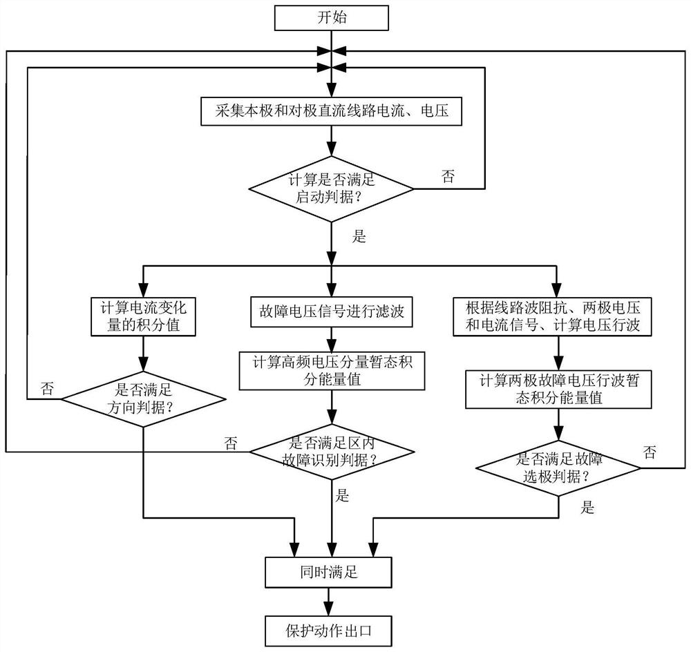
[0091] figure 1 It is a flowchart of a high-voltage direct current line protection method based on single-ended transient energy implemented according to the present invention. according to figure 1 , the protection method specifically includes the following steps:

[0092] (1) Collect the DC line voltage and current signals of the local pole and the opposite pole of the converter station.

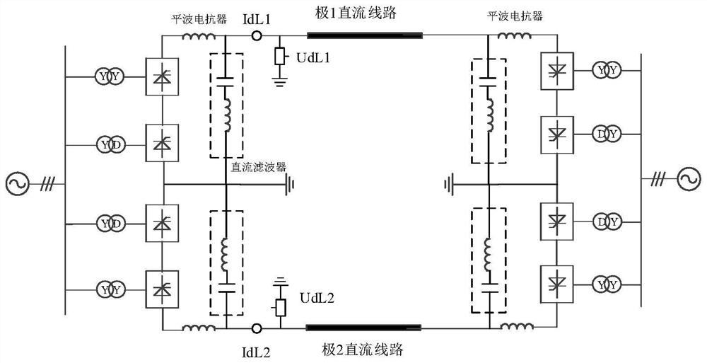
[0093] figure 2 An examp...


PUM


Abstract

The invention relates to a high-voltage direct-current transmission line protection method and device based on single-ended transient energy. The method comprises the following steps: acquiring direct-current line voltage and current signals of a local pole and an antipode of a converter station; calculating a current differential value and a current break variable of the pole as starting criteria; calculating an integral value of the current of the pole as a direction criterion; according to the pole DC line voltage, calculating a transient integral energy value as a fault area identification criterion; calculating the traveling wave transient integral energy values of the local pole and the antipode, and judging whether the local pole has a fault or not as a fault pole selection criterion; and when the direction criterion, the fault area identification criterion and the fault pole selection criterion are met at the same time, the current-level DC line protection action is performed. According to the method and the device, the ultra-high-speed detection of the direct-current line fault can be realized within 3ms, the method and the device have the advantages of high transition resistance tolerance, low sampling frequency requirement, easiness in implementation of an algorithm, no dependence on inter-station communication and the like, and the protection performance of direct-current line protection is remarkably improved.

Description

technical field [0001] The invention relates to the technical field of high-voltage direct current transmission, in particular to a method and device for protecting high-voltage direct current transmission lines based on single-end transient energy. Background technique [0002] HVDC transmission system has the advantages of large power transmission capacity, long transmission distance, and low loss, and has been widely used in long-distance power transmission and large-area grid interconnection. Due to the long transmission distance of HVDC transmission projects, the complex terrain along the way, and the fact that most of the transmission lines are overhead lines, the probability of DC line failures is greatly increased. According to statistics, the probability of DC line failures accounts for more than 50% of DC transmission system failures. Therefore, it is very important to design DC line protection with superior performance to improve the safe and stable operation of D...

Claims


Application Information

Patent Timeline
Patent Type & Authority Applications(China)
IPC IPC(8): H02H7/26H02H3/16H02H1/00
CPCH02H7/268H02H3/16H02H1/0007
Inventor 田培涛吴庆范曹森郝俊芳李亚峰张弛曹虹周泽昕罗磊范雪峰阮思烨张志刘丹
Owner XJ ELECTRIC
Learn More