
Fault detection method of shipborne antenna and device thereof

A fault detection and antenna technology, which is applied in the field of fault detection methods and devices for ship-borne antennas, and can solve the problems of complex structure, reliability, stability, low detection efficiency and large volume of ship-borne satellite antennas

Inactive Publication Date: 2015-02-04
HARXON CORP
View PDF6 Cites 3 Cited by
  • Summary
  • Abstract
  • Description
  • Claims
  • Application Information

AI Technical Summary

Problems solved by technology

[0002] The existing ship-borne satellite antenna has a complex structure and a large volume. In order to better receive satellite signals, it is usually installed at a higher position on the ship’s hull, which brings great difficulties to the daily inspection and troubleshooting of ship-borne antenna equipment. big difficulty
[0003] During the working process of the ship-borne satellite antenna, there are many key signal points that need to be collected, the amount of data is large, and the reliability of the signal is required to be high. At present, the detection can only be realized by manual methods, reliability and stability. and low detection efficiency

Method used


Image

  • Fault detection method of shipborne antenna and device thereof
  • Fault detection method of shipborne antenna and device thereof
  • Fault detection method of shipborne antenna and device thereof

Examples


Embodiment Construction

[0023] In order to make the technical problems, technical solutions and beneficial effects to be solved by the present invention clearer and clearer, the present invention will be further described in detail below in conjunction with the accompanying drawings and embodiments. It should be understood that the specific embodiments described here are only used to explain the present invention, not to limit the present invention.

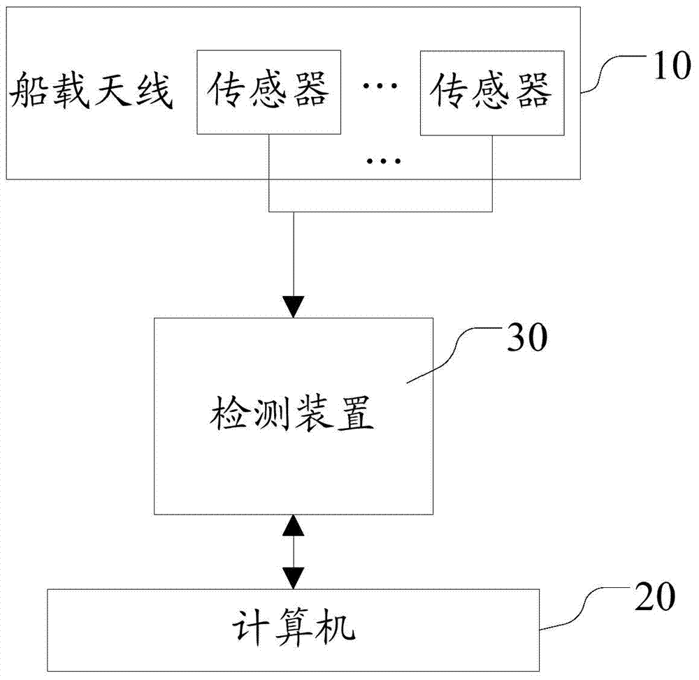
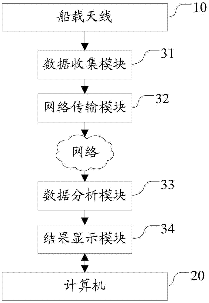
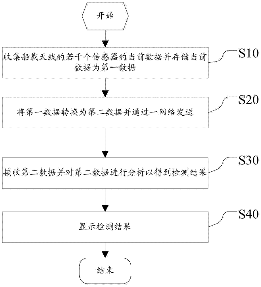
[0024] Please refer to figure 1 and figure 2 , the fault detection device 30 of the ship-borne antenna 10 of the embodiment of the present invention, hereinafter referred to as the detection device 30, is used to detect the fault of the ship-borne antenna 10, and several sensors are arranged on the ship-borne antenna 10, and several sensors are used to obtain the ship-borne The operating state of the antenna 10. The detection device 30 includes a data collection module 31 , a network transmission module 32 , a data analysis module 33 and a result dis...


PUM


Abstract

The utility model provides a fault detection device of a shipborne antenna and a method thereof. The shipborne antenna is provided with a plurality of sensors used for obtaining the operation state of the shipborne antenna. A data collecting module is used for collecting the current data of the plurality of sensors of the shipborne antenna and storing the current data as first data. A network transmission module is used for converting the first data into second data and sending the second data through a network. A data analysis module is used for receiving the second data and analyzing the second data to obtain a detection result. A result display module is used for displaying the detection result. According to the fault detection device of the shipborne antenna and the method thereof, the automatic detection of relevant data of the antenna is realized, through the reliable transmission mode, the rapid fault detection of shipborne equipment is realized, and compared with manual detection and maintenance, the time, efficiency and reliability are greatly improved.

Description

technical field [0001] The invention relates to a ship-borne antenna, in particular to a fault detection method and device for a ship-borne antenna. Background technique [0002] The existing ship-borne satellite antenna has a complex structure and a large volume. In order to better receive satellite signals, it is usually installed at a higher position on the ship’s hull, which brings great difficulties to the daily inspection and troubleshooting of ship-borne antenna equipment. big difficulty. [0003] During the working process of the ship-borne satellite antenna, there are many key signal points that need to be collected, the amount of data is large, and the reliability of the signal is required to be high. At present, the detection can only be realized by manual methods, reliability and stability. and low detection efficiency. Contents of the invention [0004] In order to solve the above problems, the present invention provides a fault detection method and device f...

Claims


Application Information

Patent Timeline
IPC IPC(8): G01D21/02G01R31/40G01H17/00H04L29/06
Inventor 王春华彭伟
Owner HARXON CORP
Learn More