Tracking type dynamic bottle cap marking method

A tracking, bottle cap technology, applied in welding equipment, laser welding equipment, metal processing equipment, etc., can solve the problems of poor feeding effect of bottle caps, unable to achieve synchronous tracking of bottle caps and bottle cap transfer devices, etc., to save Power, push and slewing fit with high precision

Active Publication Date: 2019-07-30
DEMARK (CHANGXING) INJECTION SYST CO LTD
View PDF10 Cites 3 Cited by
  • Summary
  • Abstract
  • Description
  • Claims
  • Application Information

AI Technical Summary

Problems solved by technology

[0006] The present invention provides a tracking dynamic bottle cap marking method for the deficiencies of the prior art. By setting the synchronous tracking step and cooperating with the synchronous linkage setting of the bottle cap feeding after the rotary movement, the automatic marking of the bottle cap after marking is realized. Outward output realizes the fully automatic production of bottle caps from feeding, marking to automatic output, which solves the problem that the existing technology cannot realize the synchronous tracking between the bottle caps and the bottle cap transfer device, and the bottle cap feeding effect is poor technical problem

Method used


Image

  • Tracking type dynamic bottle cap marking method
  • Tracking type dynamic bottle cap marking method
  • Tracking type dynamic bottle cap marking method

Examples


Embodiment 1

[0049]Embodiments of the present invention are described in detail below, examples of which are shown in the drawings, wherein the same or similar reference numerals designate the same or similar elements or elements having the same or similar functions throughout. The embodiments described below by referring to the figures are exemplary and are intended to explain the present invention and should not be construed as limiting the present invention.

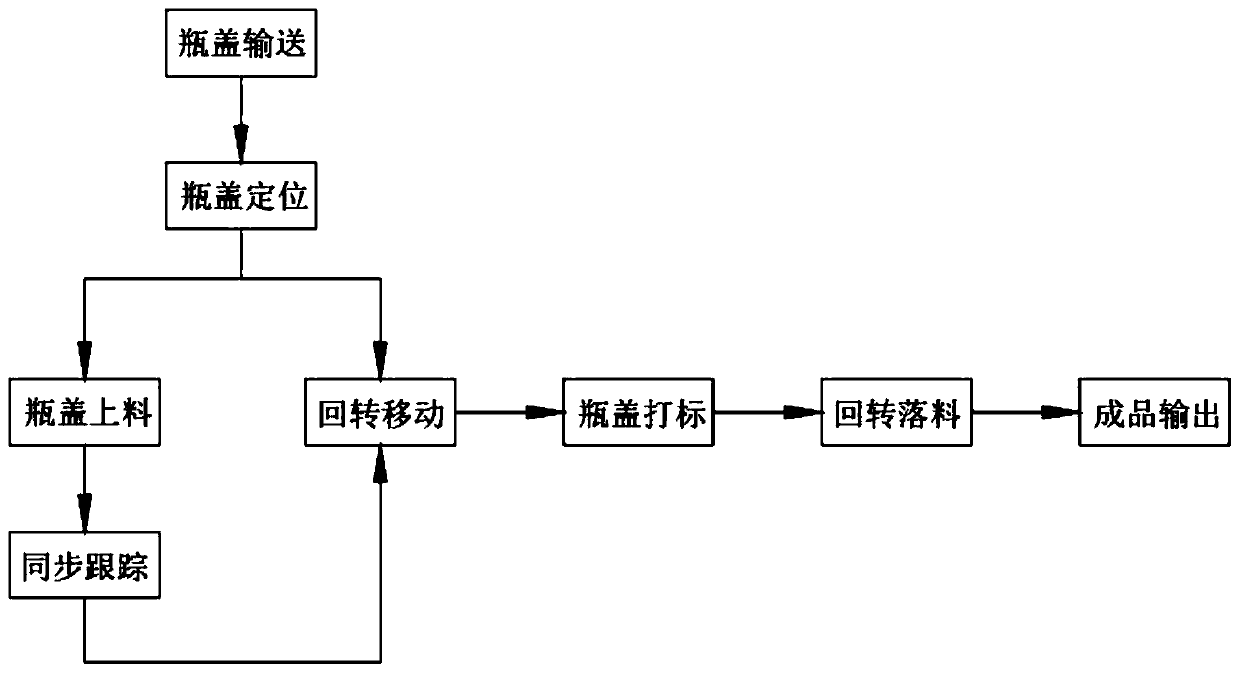
[0050] like figure 1 As shown, a tracking dynamic bottle cap marking method includes the following steps:

[0051] Step 1, bottle cap conveying, several bottle caps 10 after production and processing are entered into the bottle cap feeding track 422 and linearly transported backward in the bottle cap feeding track 422;

[0052] Step 2, bottle cap positioning, the bottle caps 10 transported in the bottle cap feeding track 422 in step 1 are transported to the pusher barrel 423, and enter the pusher barrel 423 from the feed port 422...

Embodiment 2

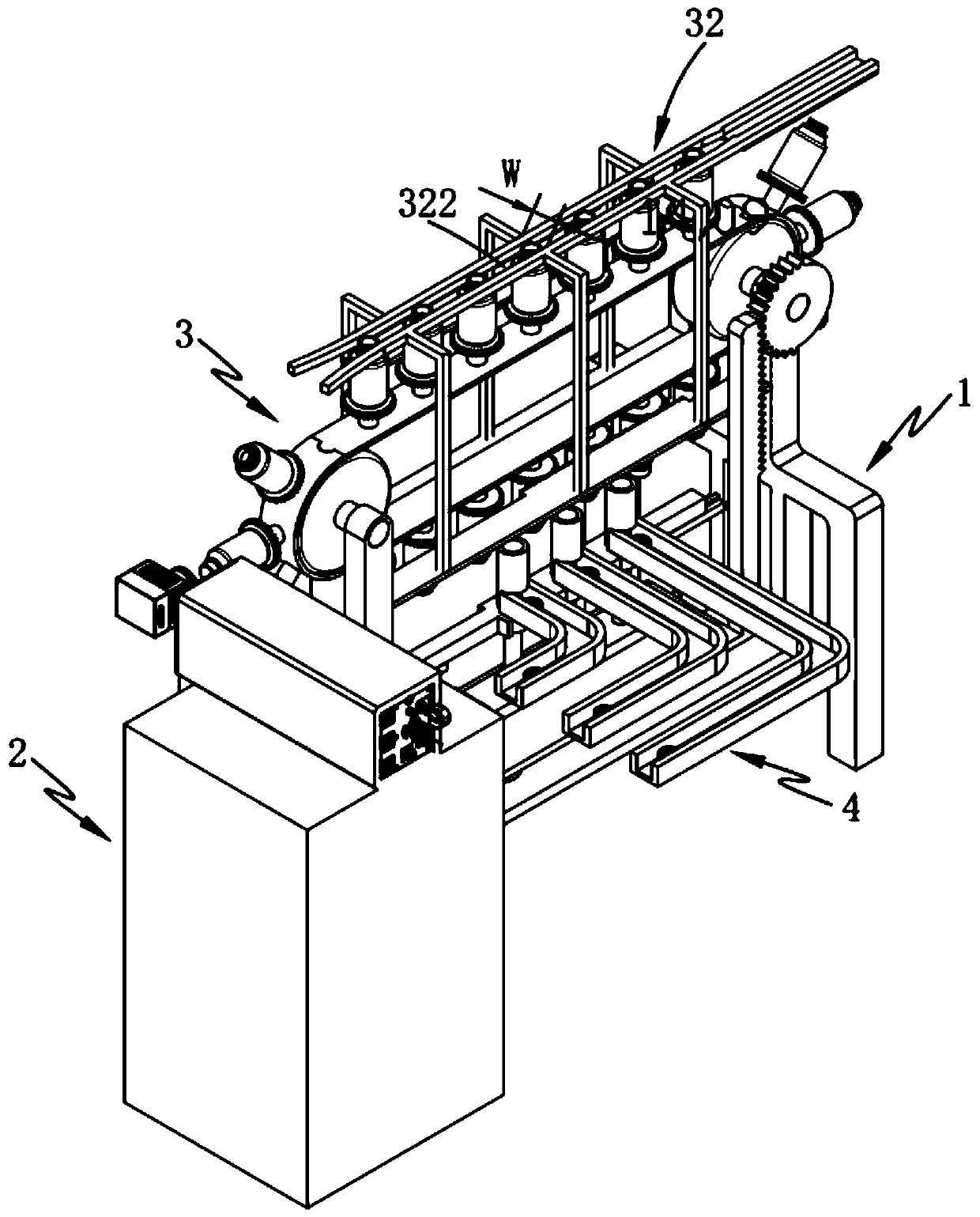
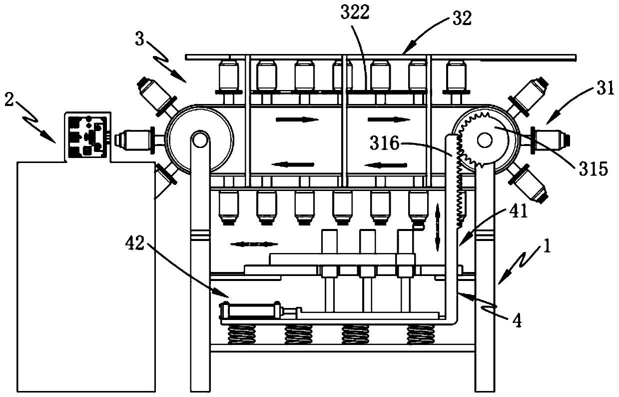
[0069] The present invention also provides a tracking type bottle cap marking equipment, such as figure 2 and 3 As shown, including bracket 1 and marking device 2, also includes:

[0070] Rotary device 3, said rotary device 3 is rotated and arranged on both ends of the length direction of said support 1, said rotary device 3 includes a rotary assembly 31 and an output assembly 32 arranged above said rotary assembly 31, said rotary assembly 31 Transport the bottle caps 10 that need to be marked in a rotary manner, and enter the output assembly 32 for outward output after marking at the marking device 2 during transportation; and

[0071] Feeding device 4, described feeding device 4 is slidably arranged on the described support 1, and this feeding device 4 comprises the interval pusher assembly 41 that is slidably arranged on the height direction of described support 1 and is slidably arranged on the interval pusher assembly 41. The tracking assembly 42 in the length directio...


PUM


Abstract

The invention provides a tracking type dynamic bottle cap marking method. The method comprises the steps of bottle cap conveying, bottle cap positioning, bottle cap feeding, rotary moving, synchronoustracking, bottle cap marking, rotary discharging and finished product output. Through the arrangement of the synchronous tracking step and the synchronous linkage arrangement of the bottle cap feeding after the rotary moving, the automatic outward output of bottle caps after the bottle caps are marked is achieved, the full-automatic production of the bottle caps from feeding, marking to automaticoutput is achieved; and the technical problems that the synchronous tracking between the bottle caps and a bottle cap transferring device cannot be achieved and the bottle cap feeding effect is poorin the prior art are solved.

Description

technical field [0001] The invention relates to the technical field of bottle cap processing, in particular to a tracking dynamic bottle cap marking method. Background technique [0002] At present, in the bottle cap production industry, more and more bottle caps use laser marking barcodes, QR codes, patterns, text, numbers, letters and other content on the surface or inside. In the marking process, at present, a set of bottle cap auxiliary equipment (cap sorting and vacuum conveyor belt) is usually used together with one or two sets of laser marking equipment for online marking. Or the production capacity of double-head online marking, many bottle cap manufacturers have to increase equipment in order to match the production capacity of the main machine, resulting in waste of space, cost, energy consumption, and personnel. The production cost of modern bottle cap production enterprises is getting lower and lower, and the labor demand is getting less and less, and the requir...

Claims


Application Information

Patent Timeline
Patent Type & Authority Applications(China)
IPC IPC(8): B23K26/362B23K26/70
CPCB23K26/362B23K26/702
Inventor 王巍植
Owner DEMARK (CHANGXING) INJECTION SYST CO LTD
Why Eureka
Try Eureka