A tracking dynamic bottle cap marking method
A tracking type, bottle cap technology, applied in metal processing equipment, welding equipment, manufacturing tools, etc., can solve the problems of unable to achieve synchronous tracking of bottle caps and bottle cap transfer devices, poor feeding effect of bottle caps, etc. High precision and power saving effect with slewing
- Summary
- Abstract
- Description
- Claims
- Application Information
AI Technical Summary
Problems solved by technology
Method used
Image
Examples
Embodiment 1
[0049] Embodiments of the present invention are described in detail below, examples of which are shown in the drawings, wherein the same or similar reference numerals designate the same or similar elements or elements having the same or similar functions throughout. The embodiments described below by referring to the figures are exemplary and are intended to explain the present invention and should not be construed as limiting the present invention.
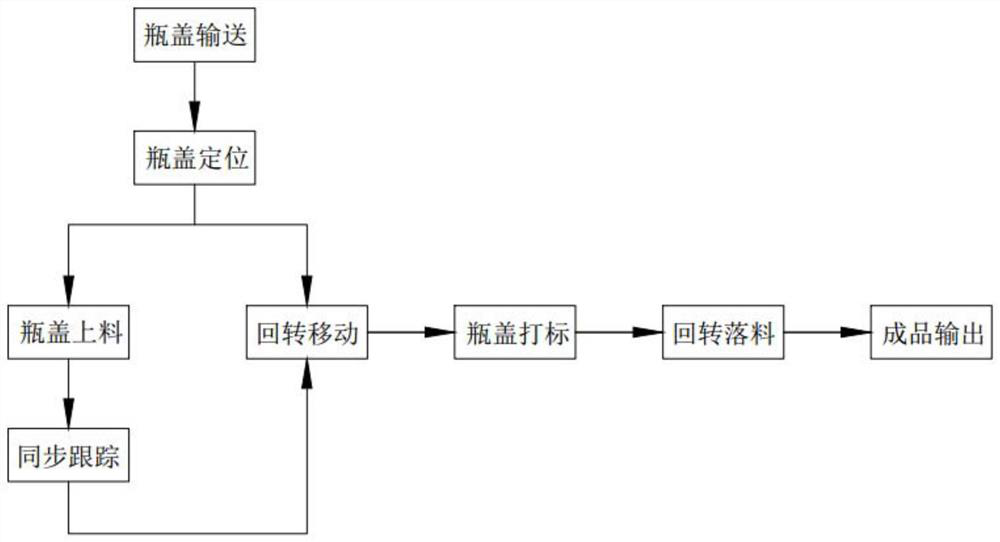
[0050] like figure 1As shown, a tracking dynamic bottle cap marking method includes the following steps:
[0051] Step 1, conveying the bottle caps. After the production and processing, several bottle caps 10 enter the bottle cap feeding track 422 and are linearly transported backward in the bottle cap feeding track 422;
[0052] Step 2, bottle cap positioning, the bottle caps 10 transported in the bottle cap feeding track 422 in step 1 are transported to the pusher barrel 423, and enter the pusher barrel 423 from the feed port ...
Embodiment 2
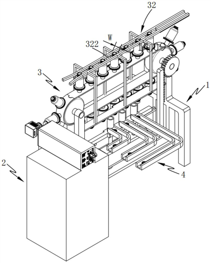
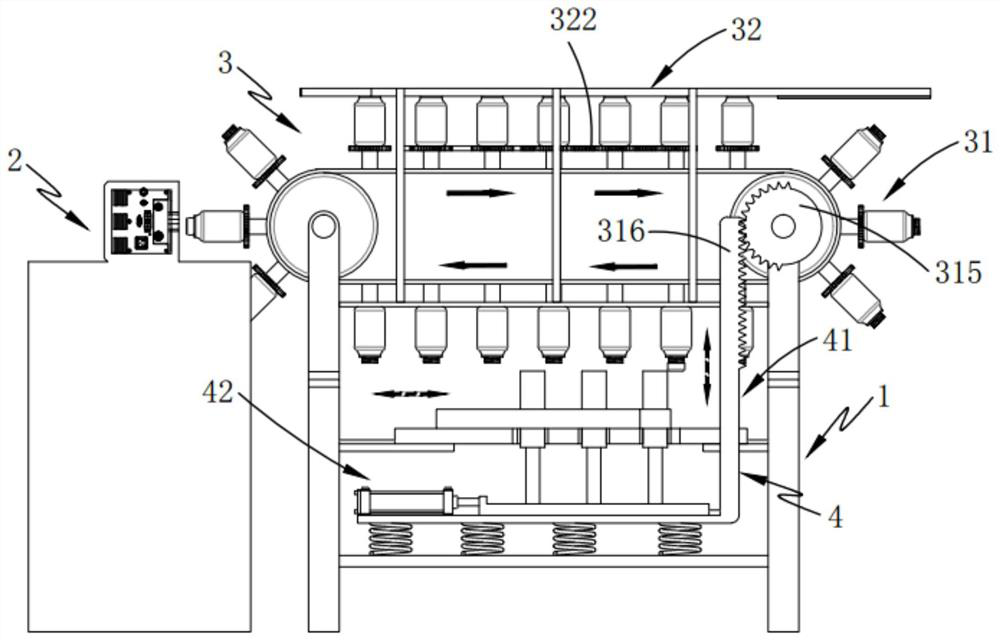
[0069] The present invention also provides a tracking type bottle cap marking equipment, such as figure 2 and 3 As shown, including bracket 1 and marking device 2, also includes:
[0070] Rotary device 3, described rotary device 3 is rotated and arranged on the two ends of the longitudinal direction of described support 1, and this rotary device 3 comprises rotary assembly 31 and is arranged on the output assembly 32 above described rotary assembly 31, and described rotary assembly 31 Transport the bottle caps 10 that need to be marked in a rotary manner, and enter the output assembly 32 for outward output after marking at the marking device 2 during transportation; and
[0071] Feeding device 4, described feeding device 4 is slidably arranged on the described support 1, and this feeding device 4 comprises the interval pusher assembly 41 that is slidably arranged on the height direction of described support 1 and is slidably arranged on the interval pusher assembly 41. The ...
PUM
 Abstract
Description
Claims
Application Information
 - R&D
- Intellectual Property
- Life Sciences
- Materials
- Tech Scout
- Unparalleled Data Quality
- Higher Quality Content
- 60% Fewer Hallucinations
Browse by: Latest US Patents, China's latest patents, Technical Efficacy Thesaurus, Application Domain, Technology Topic, Popular Technical Reports.
© 2025 PatSnap. All rights reserved.Legal|Privacy policy|Modern Slavery Act Transparency Statement|Sitemap|About US| Contact US: help@patsnap.com


