Loading mechanism of automatically-loading mixing truck, and loading and unloading method thereof
A mixer truck and self-feeding technology, which is applied to cement mixing devices, chemical instruments and methods, and sales of raw material supply devices, etc., can solve problems such as single function and material leakage, and achieve the effect of improving operation efficiency and reducing operation steps
- Summary
- Abstract
- Description
- Claims
- Application Information
AI Technical Summary
Problems solved by technology
Method used
Image
Examples
Embodiment 1
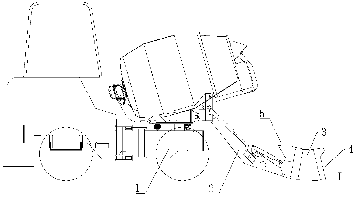
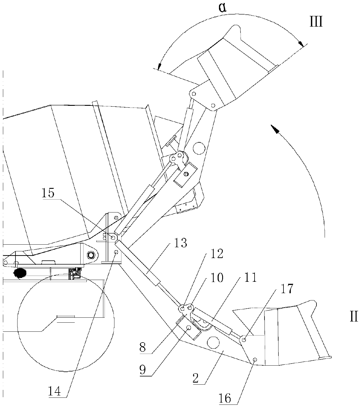
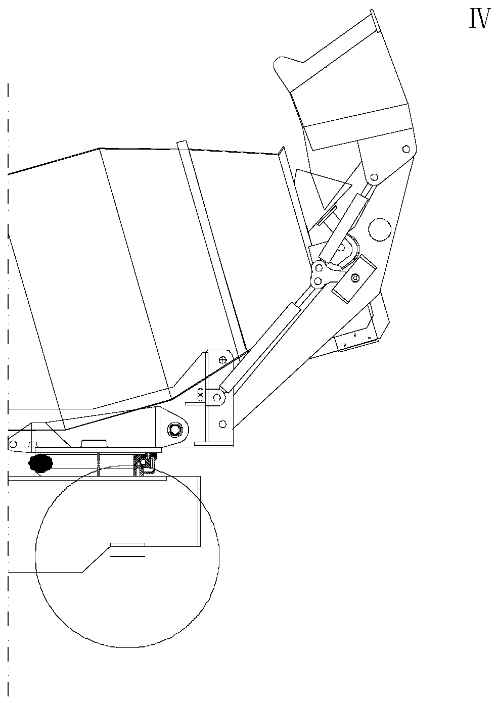
[0038] Such as Figure 1-Figure 4 Commonly shown, it is an embodiment of the feeding mechanism of the self-loading mixer truck of the present invention. For the convenience of description, Figure 2-Figure 4 The left part of the self-loading mixer truck has been removed. It should be noted that the subsequent "before" refers to the figure 1 On the right side of the middle, "after" refers to the figure 1 in the left.
[0039] The feeding mechanism first includes a boom 2, the rear end of the boom 2 is connected to the car body 1 through a fourth hinge point 14, and the boom 2 is driven by a boom oil cylinder (not shown in the figure) to realize lifting. The structure in which the boom cylinder drives the boom 2 belongs to a relatively common mechanical structure in the field, and will not be repeated here.
[0040] The front end of the boom 2 is connected with the upper hopper 3 through the sixth hinge point 16, and the structure of the upper hopper 3 is as follows: Figur...
Embodiment 2
[0050] This embodiment is the loading and unloading method of the feeding mechanism shown in Embodiment 1. What this method accomplishes is to feed the materials on the ground into the mixing tank, and its basic action steps are state I → state III → state IV Of course, after completing state I, the second oil cylinder 13 can be shortened first to make the upper hopper 3 warp, and then proceed to state III. Specifically, the overall operation steps include:
[0051] S1. The boom cylinder drives the boom 2, and puts the upper hopper 3 flat on the ground. At this time, the length of the first cylinder 11 and the second cylinder 13 is defined as the initial length;
[0052] S2. The car body 1 moves forward, and the materials on the ground are shoveled into the upper hopper 3;
[0053] S3. Appropriately shorten the second oil cylinder 13, so that the upper hopper 3 is tilted backward;
[0054] S4. The boom oil cylinder drives the boom 2 to lift to the highest, and keeps the leng...
Embodiment 3
[0059] This embodiment is another loading and unloading method of the loading mechanism shown in Embodiment 1. This method completes the loading of materials on the ground onto other transport vehicles or equipment, and its basic action steps are state I → State III → State V is the same as the second embodiment. After the state I is completed, the second oil cylinder 13 can be shortened to make the upper hopper 3 warp, and then proceed to state III. Specifically, the overall operation steps include:
[0060] S1. The boom cylinder drives the boom 2, and puts the upper hopper 3 flat on the ground. At this time, the length of the first cylinder 11 and the second cylinder 13 is defined as the initial length;
[0061] S2. The car body 1 moves forward, and the materials on the ground are shoveled into the upper hopper 3;
[0062] S3. Appropriately shorten the second oil cylinder 13, so that the upper hopper 3 is tilted backward;
[0063] S4. The boom oil cylinder drives the boom ...
PUM
 Abstract
Description
Claims
Application Information
 - R&D
- Intellectual Property
- Life Sciences
- Materials
- Tech Scout
- Unparalleled Data Quality
- Higher Quality Content
- 60% Fewer Hallucinations
Browse by: Latest US Patents, China's latest patents, Technical Efficacy Thesaurus, Application Domain, Technology Topic, Popular Technical Reports.
© 2025 PatSnap. All rights reserved.Legal|Privacy policy|Modern Slavery Act Transparency Statement|Sitemap|About US| Contact US: help@patsnap.com


