
Hinged structure

A hinged, anti-off structure technology, applied in the mechanical field, can solve the problems of increased production process and the influence of hinged parts, and achieve the effects of convenient processing, quick disassembly and simplified structure

Active Publication Date: 2019-07-30
ZHEJIANG TOPSUN LOGISTIC CONTROL CO LTD
View PDF14 Cites 1 Cited by
  • Summary
  • Abstract
  • Description
  • Claims
  • Application Information

AI Technical Summary

Problems solved by technology

[0006] The purpose of the present invention is to solve the above-mentioned problems in the existing technology, and propose a new type of hinge structure. The present invention solves the problem of increased production process caused by the need to fix the hinge on the hinged object when the hinge is detachable, and the influence of the hinge on the hinge. Object usage etc.

Method used


Image

  • Hinged structure
  • Hinged structure
  • Hinged structure

Examples


Embodiment 1

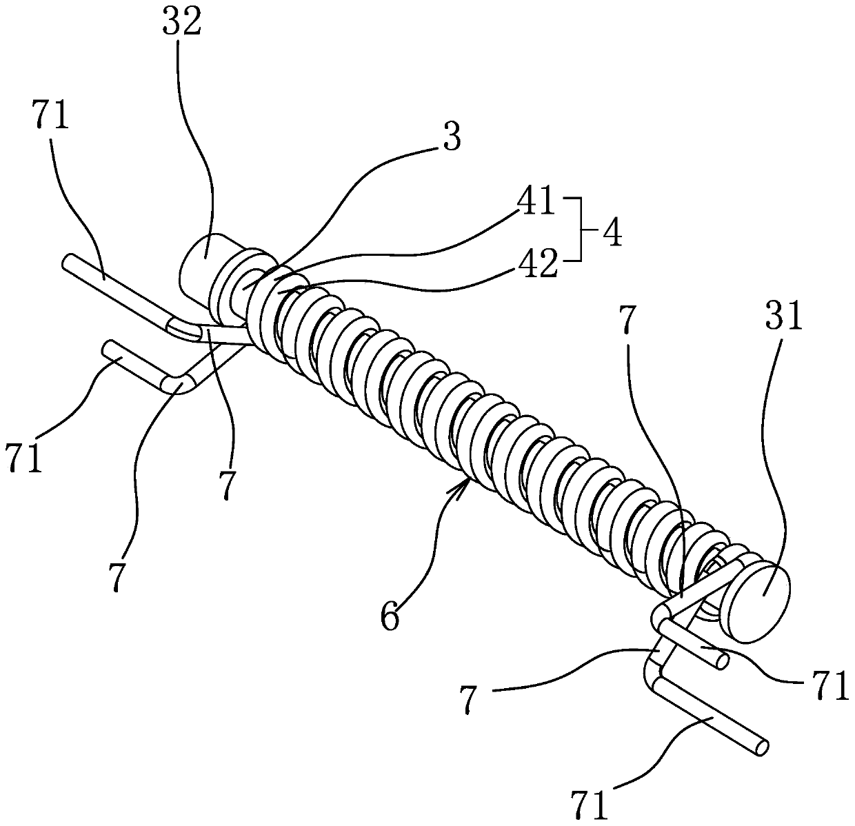
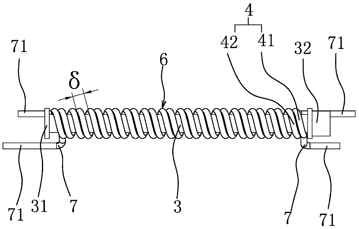
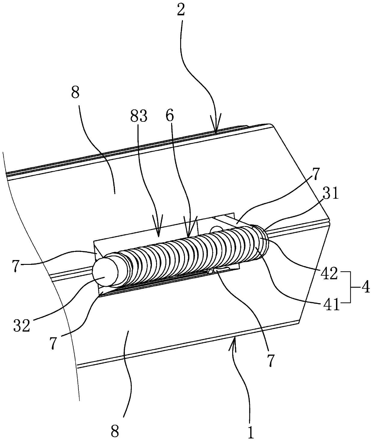
[0043] This hinge structure is used to hinge part one 1 and part two 2, such as figure 1 and figure 2 As shown, the hinged structure comprises pin shaft 3, and pin shaft 3 is sheathed with two torsion springs 4, and two torsion springs 4 are respectively torsion spring one 41 and torsion spring two 42, and torsion spring one 41 and torsion spring two 42 can Perform relative rotation. Torsion spring one 41 and torsion spring two 42 are all formed by wire winding, and torsion spring one 41 and torsion spring two 42 all include the helical part 6 that is rotatably sleeved on the bearing pin 3 and two helical parts that are respectively formed by the helical part 6. The insertion arm 7 extended from the end, the insertion arm 7 is L-shaped, one end of the insertion arm 7 is connected to the spiral part 6, and the other end of the insertion arm 7 is bent in a direction away from the spiral part 6 to form an insertion section 71 , and the length direction of the inserting section...

Embodiment 2

[0054] The structure and principle of this embodiment are basically the same as that of Embodiment 1, the difference is that: Figure 11 As shown, part one 1 is provided with two insertion holes 1a, part two 2 is provided with two insertion holes 2a, and the insertion sections 71 of torsion spring one 41 and two insertion arms 7 are respectively inserted in In the two insertion holes 1a, the insertion sections 71 of the two insertion arms 7 of the torsion spring 2 42 are respectively inserted in the two insertion holes 2a. When carrying out the processing of part one 1 and part two 2, only need to process out inserting hole one 1a or inserting hole two 2a on part one 1 and part two 2, it is comparatively convenient to manufacture. In the actual manufacturing process, the aperture of the first insertion hole 1a can be greater than or equal to the diameter of the corresponding insertion section 71, and the aperture of the second insertion hole 2a can also be greater than or equa...

Embodiment 3

[0056] The structure and principle of this embodiment are basically the same as that of Embodiment 1, except that the first torsion spring 41 and the second torsion spring 42 are wound by metal wires of the same diameter, and the axial gap δ between the two is equal, and the torsion spring 2 The axial gap δ of spring one 41 spiral portion 6 is 1.5 times of the wire diameter of torsion spring two 42 .


PUM


Abstract

The invention provides a hinged structure and belongs to the technical field of machines. The hinged structure solves the problems that in the prior art, during detachable hinging, production processes are increased due to the fact that it is needed to fixedly connect a hinged piece to a hinged object, and the hinged piece affects use of the hinged object. The hinged structure is used for hinginga first part and a second part; the hinged structure comprises a pin shaft and two torsional springs; the two torsional springs are connected in the manner that the pin shaft passes through through holes of the two torsional springs; the two ends of one torsional spring are connected to the first part due to interested connection cooperation; and the two ends of the other torsional spring are connected to the second part due to inserted connection cooperation. The hinged structure has the beneficial effects of being convenient to disassemble, wide in rotating range, low in cost and the like.

Description

technical field [0001] The invention belongs to the technical field of machinery and relates to a hinge structure. Background technique [0002] Hinge is a very common connection method in the mechanical field, and when two parts are hinged, a related hinge structure is required. [0003] The conventional hinged structure includes directly hinged two parts through a rotating shaft, or realizes the hinged joint of two parts through a hinge. For example, a gamepad and its button structure disclosed in Chinese patent literature (authorized announcement number: CN207871496U; application number: 201820204547.7), the gamepad includes buttons and a bracket suitable for being installed on the gamepad PCB board, and the buttons are equipped with hinged The ear, the hinged ear and the hinged seat of the bracket are hinged together through a pin shaft. A torsion spring is arranged on the pin shaft. One end of the torsion spring leans against the hinged seat, and the other end of the t...

Claims


Application Information

Patent Timeline
Patent Type & Authority Applications(China)
IPC IPC(8): F16C11/12
CPCF16C11/12
Inventor 阮卜琴牛胜良
Owner ZHEJIANG TOPSUN LOGISTIC CONTROL CO LTD
Learn More