
Alcohol injection device

A flow control device and tank technology, applied in pipeline systems, gas/liquid distribution and storage, mechanical equipment, etc., can solve the problems of increasing pipeline pressure drop, large labor intensity, blocking and stopping transportation, etc., and reduce manufacturing and use. Cost, reduce labor intensity, and avoid the effect of methanol spillage to harm the environment

Active Publication Date: 2020-10-16
大庆市庆普达石油技术服务有限公司
View PDF11 Cites 0 Cited by
  • Summary
  • Abstract
  • Description
  • Claims
  • Application Information

AI Technical Summary

Problems solved by technology

[0002] The natural gas used for combustion in oilfield stations is a mixture of alkanes, with methane accounting for about 90 percent, carbon dioxide, hydrogen sulfide, nitrogen and water vapor, and a small amount of olefins and light oil. Untreated natural gas contains water, which will form hydrates under certain temperature and pressure conditions, which will increase the pressure drop of the pipeline, especially in winter or even blockage and shutdown, causing great economic losses to oil field production, and there are great safety hazards. Therefore, there is an increasing demand for alcohol injection devices
[0003] In the field of methanol filling, some of the currently used filling methods are non-powered devices, which are filled by external moisture pressure, which cannot realize the demand control of self-controlled filling, so the filling volume is not easy to control, and manual work is required in the early stage Inverting tank filling not only brings greater labor intensity, but also has the problem of safety and environmental protection of methanol pouring down, and it is not convenient to observe the amount of methanol added and used, so that it is impossible to replenish methanol quantitatively and in a timely manner. The use of methanol was found, therefore, an alcohol injection device was proposed to solve the above problems

Method used


Image

  • Alcohol injection device
  • Alcohol injection device
  • Alcohol injection device

Examples


Embodiment 1

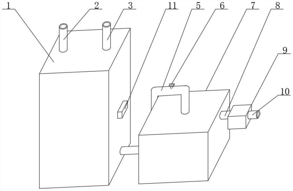
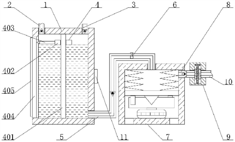
[0028] see figure 1 , figure 2 , Figure 4 , Figure 6 and Figure 7 , the present invention provides a technical solution:

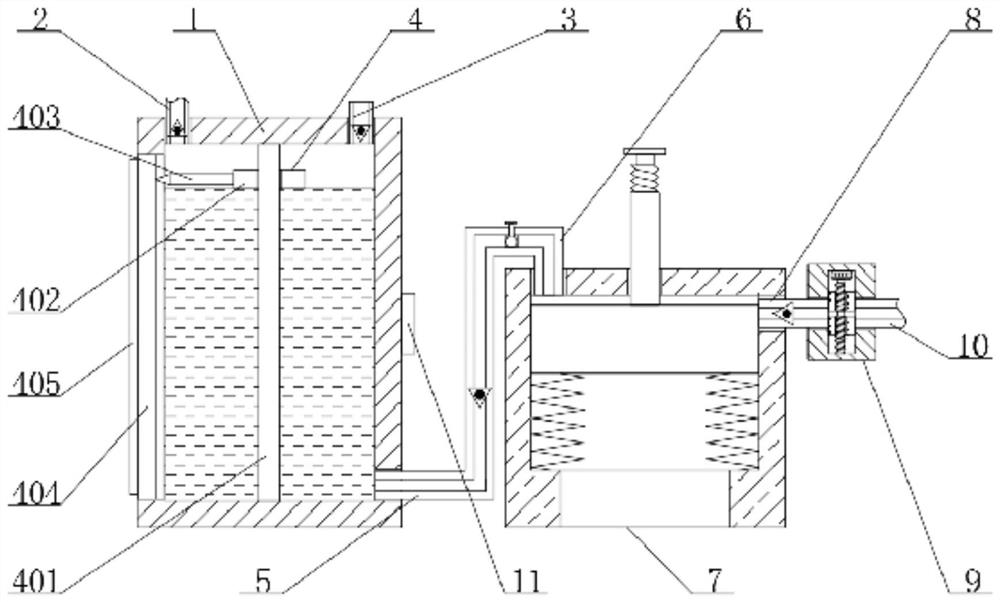
[0029]The alcohol injection device comprises a tank body 1, the top surface of the tank body 1 is connected with an air inlet pipe 2 and an air outlet pipe 3 arranged left and right, and a liquid level observation device 4 is provided inside the tank body 1, and the liquid level observation device 4 includes a fixed shaft 401, Floating plate 402, pointer 403, toughened glass plate 404 and scale 405, the inside of the tank body 1 is fixedly connected with a fixed shaft 401, the outside of the fixed shaft 401 is slidingly connected with a floating plate 402, the left end of the floating plate 402 is fixedly connected with a pointer 403, the pointer A tempered glass plate 404 is slidingly connected to the left end of 403, and the tempered glass plate 404 is fixedly connected to the tank body 1, and a scale 405 is fixedly connected to the left end of t...

Embodiment 2

[0033] see image 3 , Figure 5 and Figure 7 , the present invention provides a technical solution:

[0034] The alcohol injection device comprises a tank body 1, the top surface of the tank body 1 is connected with an air inlet pipe 2 and an air outlet pipe 3 arranged left and right, and a liquid level observation device 4 is provided inside the tank body 1, and the liquid level observation device 4 includes a fixed shaft 401, Floating plate 402, pointer 403, toughened glass plate 404 and scale 405, the inside of the tank body 1 is fixedly connected with a fixed shaft 401, the outside of the fixed shaft 401 is slidingly connected with a floating plate 402, the left end of the floating plate 402 is fixedly connected with a pointer 403, the pointer A tempered glass plate 404 is slidingly connected to the left end of 403, and the tempered glass plate 404 is fixedly connected to the tank body 1, and a scale 405 is fixedly connected to the left end of the tempered glass plate 4...


PUM


Abstract

The invention relates to the technical field of methanol injection, in particular to a methanol injection device. The methanol injection device comprises a tank body, wherein the top end face of the tank body communicates with an air inlet pipe and an air outlet pipe which are arranged in the left-and-right manner, a liquid level observation device is arranged inside the tank body, the bottom endof the right end face of the tank body communicates with a liquid inlet pipe, the inner side of the liquid inlet pipe is fixedly connected with a control valve, and the other end of the liquid inlet pipe communicates with an injection unit. The right end face of the injection unit communicates with a liquid outlet pipe, the other end of the liquid outlet pipe communicates with a flow control device, and the right end face of the flow control device communicates with a connecting pipe. The middle position of the right end face of the tank body is fixedly connected with a controller. In the methanol injection device, by arranging a sliding block and coordinating the arrangement with screwed connection of the sliding block and a second threaded shaft, screwed connection of the sliding block and a third threaded shaft and sliding connection of the sliding block and a supporting box, a second motor is controlled by the controller to realize the adjustment of methanol injection flow, and methanol injection is facilitated according to the demands.

Description

technical field [0001] The invention relates to the technical field of methanol injection, in particular to an alcohol injection device. Background technique [0002] The natural gas used for combustion in oilfield stations is a mixture of alkanes, with methane accounting for about 90 percent, carbon dioxide, hydrogen sulfide, nitrogen and water vapor, and a small amount of olefins and light oil. Untreated natural gas contains water, which will form hydrates under certain temperature and pressure conditions, which will increase the pressure drop of the pipeline, especially in winter or even blockage and shutdown, causing great economic losses to oil field production, and there are great safety hazards. Therefore, the demand for alcohol injection devices is increasing day by day. [0003] In the field of methanol filling, some filling methods currently used are non-powered devices, which rely on external moisture pressure for filling, which cannot realize the demand control ...

Claims


Application Information

Patent Timeline
Patent Type & Authority Patents(China)
IPC IPC(8): F17D1/02F17D3/12
CPCF17D1/02F17D3/12
Inventor 付嘉宁付学才
Owner 大庆市庆普达石油技术服务有限公司
Learn More