Communication line erector

A technology of communication lines and erectors, applied in the field of communication, can solve the problem that different communication lines cannot be erected at different heights

Active Publication Date: 2019-07-30
河北明通通信器材有限公司
View PDF6 Cites 4 Cited by
  • Summary
  • Abstract
  • Description
  • Claims
  • Application Information

AI Technical Summary

Problems solved by technology

However, this wire erector cannot erect different communication lines at different heights, and cannot make the lines easy to move between multiple layers when erecting

Method used


Image

  • Communication line erector
  • Communication line erector
  • Communication line erector

Examples


specific Embodiment approach 1

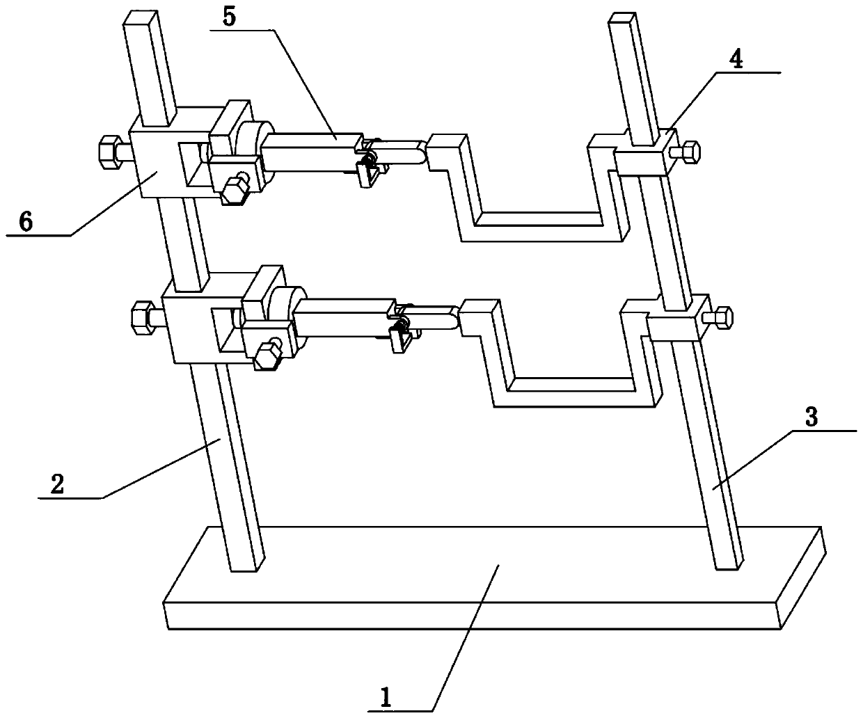
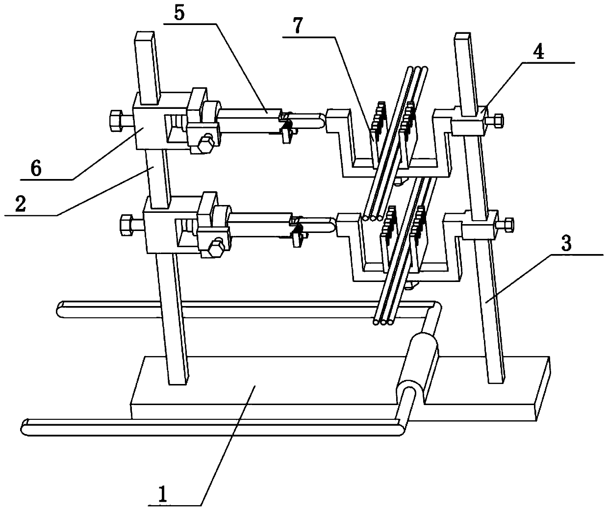
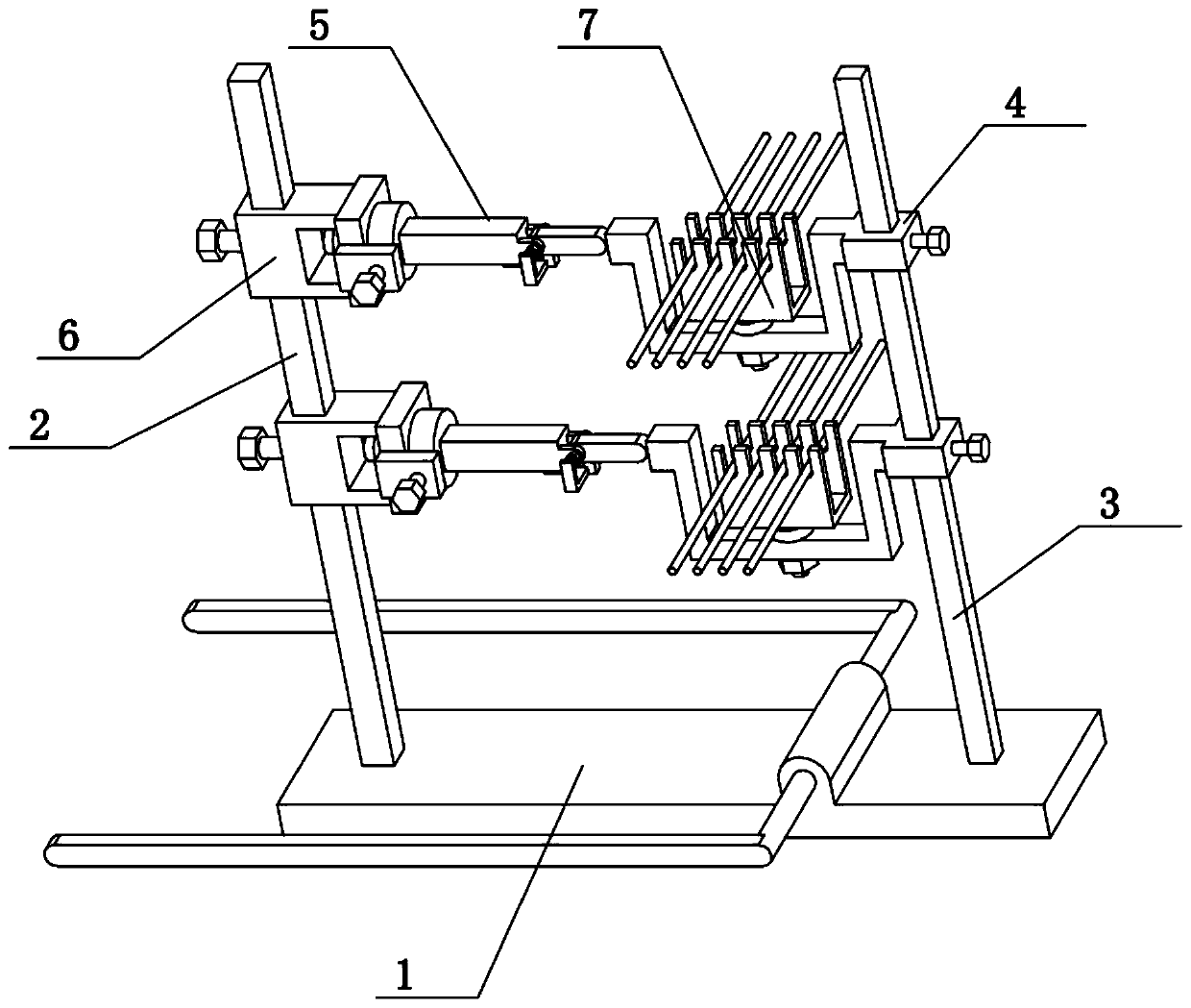
[0043] Combine below Figure 1-16 Describe this embodiment, the present invention relates to the field of communication, more specifically a communication line erector, including a base plate 1, a left column 2, a right column 3, a wire frame 4, a horizontal column 5, a rotating rod 503 and a slider 6. The present invention is provided with multiple layers, so that different communication lines can be erected at different heights, and the lines can be easily moved between multiple layers during erection.

[0044]The left and right ends of the base plate 1 are respectively fixedly connected with a left column 2 and a right column 3, a plurality of wire racks 4 are arranged on the right column 3, a plurality of sliders 6 are arranged on the left column 2, and a plurality of sliders 6 The right ends of each are fixedly connected with cross-columns 5, and the plurality of cross-columns 5 are respectively corresponding to the plurality of wire racks 4, and the right ends of the plu...

specific Embodiment approach 2

[0046] Combine below Figure 1-16 To illustrate this embodiment, the right ends of the plurality of wire racks 4 are all slidably connected to the right upright post 3, and the right ends of the plurality of wire racks 4 are all threadedly connected with fastening screws 1, and the plurality of fastening screws 1 are all supported on the right side. On the upright post 3, thereby a plurality of wire racks 4 are fixed on the right upright post 3, and a plurality of sliders 6 are all slidably connected on the left upright post 2, and a plurality of sliders 6 are all threadedly connected with fastening screws II, and a plurality of The fastening screws II are all supported on the left column 2, thereby fixing a plurality of slide blocks 6 on the left column 2. A plurality of wire racks 4 can slide vertically on the right column 3, and fastening screw 1 is used to fix the wire rack 4 on the right column 3; a plurality of slide blocks 6 can vertically slide on the left column 2, ti...

specific Embodiment approach 3

[0048] Combine below Figure 1-16 To illustrate this embodiment, the plurality of wire racks 4 are all provided with a wire rack 401 . When the communication line rack is placed on the wire rack 4, the communication line should be placed on the wire rack 401 to prevent the communication line from sliding from the wire rack 4 left and right.


PUM


Abstract

The invention relates to the field of communication, in particular to a communication line erector which comprises a base plate, a left upright post, a right upright post, a line frame, a transverse post, a rotating rod and a sliding block. The communication line erector is provided with a plurality of layers, can erect different communication lines at different heights, and is convenient for thelines to move among the layers when being erected. The left end and the right end of the base plate are respectively and fixedly connected with the left upright post and the right upright post, a plurality of line frames are arranged on the right upright post, a plurality of sliding blocks are arranged on the left upright post, the right ends of the sliding blocks are fixedly connected with the transverse posts, the plurality of transverse posts respectively correspond to the plurality of line frames, and the right ends of the plurality of transverse posts are all hinged with the rotating rod.

Description

technical field [0001] The invention relates to the field of communication, more specifically a communication line erector. Background technique [0002] The application number is CN201320151201.2, which discloses an insulated wire wire hanger. The utility model relates to an insulated wire wire hanger. The main body and the horizontal connection surfaces respectively located at the two ends of the main body; two terminal support columns, respectively fixedly connected to the two horizontal connection surfaces of the base; a cable clamp, fixedly connected to one of the terminal support columns On the horizontal connection surface, one end of the insulated wire waiting to be stripped can be fastened by the cable clamp; an end support seat is fixedly connected to the horizontal connection surface of the other end support column, and the other end of the insulated wire can be Set up in the U-shaped notch on the end support seat. By arranging the U-shaped splint and the spring...

Claims


Application Information

Patent Timeline
Patent Type & Authority Applications(China)
IPC IPC(8): H02G1/02
CPCH02G1/02
Inventor 郑乐
Owner 河北明通通信器材有限公司
Why Eureka
Try Eureka