Check patentability & draft patents in minutes with Patsnap Eureka AI!

Power switch control circuit

A technology for controlling circuits and power switches, which is applied in the direction of control/regulation systems, electrical components, and adjustment of electrical variables, and can solve problems such as inability to adjust power switches

Inactive Publication Date: 2019-07-30
KUNSHAN BRANCH INST OF MICROELECTRONICS OF CHINESE ACADEMY OF SCI
View PDF8 Cites 0 Cited by
  • Summary
  • Abstract
  • Description
  • Claims
  • Application Information

AI Technical Summary

Problems solved by technology

In the prior art, the power switch is generally controlled by Pulse Width Modulation (PWM), but with this method, the power switch cannot be adjusted in real time to ensure that the power switch is within a controllable range. within

Method used


Image

  • Power switch control circuit
  • Power switch control circuit

Examples


Embodiment Construction

[0025] The following will clearly and completely describe the technical solutions in the embodiments of the present invention with reference to the accompanying drawings in the embodiments of the present invention. Obviously, the described embodiments are only some of the embodiments of the present invention, not all of them. Based on the embodiments of the present invention, all other embodiments obtained by persons of ordinary skill in the art without making creative efforts belong to the protection scope of the present invention.

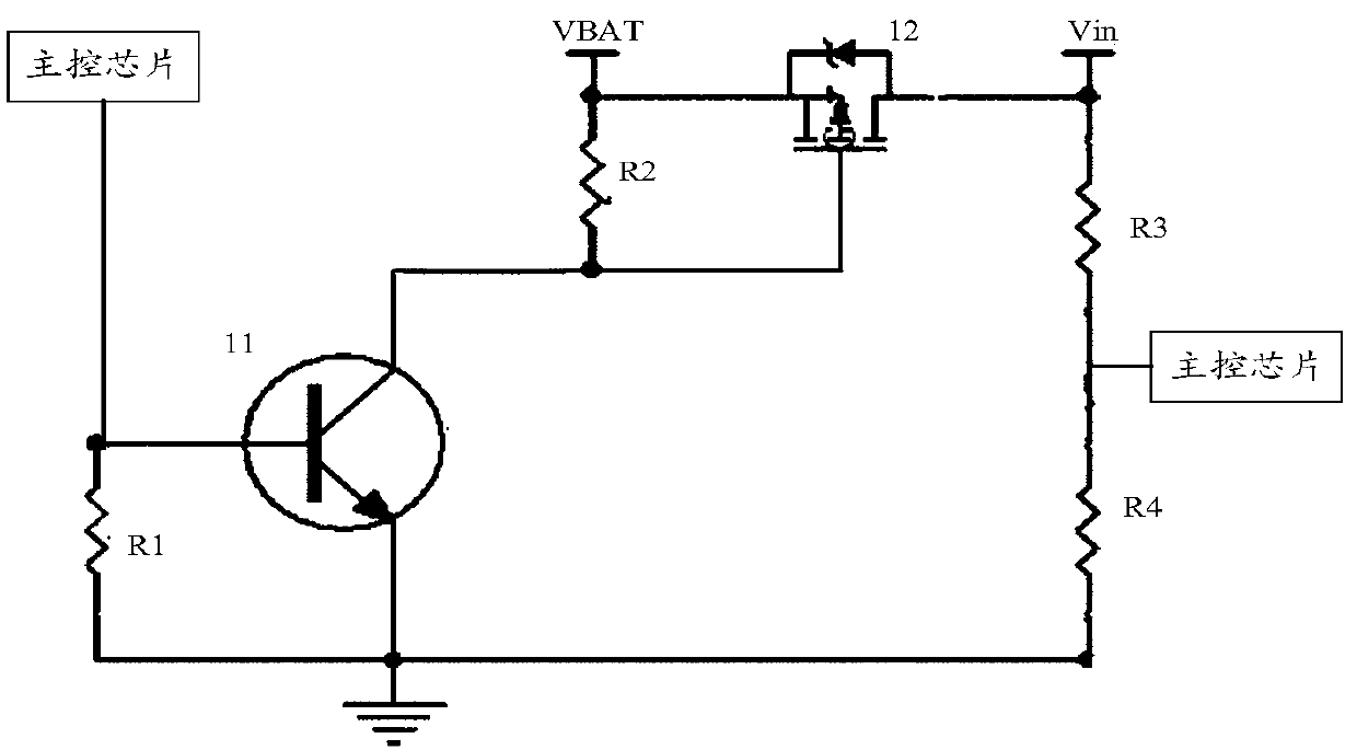
[0026] The embodiment of the present invention discloses a power switch control circuit, such as figure 1 As shown, the circuit includes:

[0027] The first controllable switch 11, the second controllable switch 12, the first resistor R1, the second resistor R2, the third resistor R3 and the fourth resistor R4;

[0028] The first end of the main control chip is respectively connected to the first end of the first resistor R1 and the control end ...


PUM


Abstract

The invention discloses a power switch control circuit. The power switch control circuit comprises a first controllable switch, a second controllable switch, a first resistor, a second resistor, a third resistor and a fourth resistor; the first end of a main control chip is connected with the first end of the first resistor and the control end of the first controllable switch separately; the second end of the first resistor is connected with the second end of the first controllable switch, and the second end of the first controllable switch is grounded; the first end of the first controllableswitch is connected with the first end of the second resistor and the control end of the second controllable switch separately; the second end of the second resistor is connected with the input end ofthe power supply and the first end of the second controllable switch separately; the second end of the second controllable switch is connected with the output end of the power supply, and the outputend of the power supply is connected with the first end of the third resistor; the second end of the third resistor is connected with the second end of the main control chip and the first end of the fourth resistor separately; and the second end of the fourth resistor is connected with the second end of the first controllable switch. The power switch can be controlled in real time through the circuit.

Description

technical field [0001] The invention relates to the technical field of power electronics, in particular to a power switch control circuit. Background technique [0002] The power switch is a switch that can maintain a stable output voltage. Due to its stable performance, it is widely used in various industrial automation controls, such as: military equipment, medical equipment, scientific research fields, etc. In the prior art, the power switch is generally controlled by Pulse Width Modulation (PWM), but with this method, the power switch cannot be adjusted in real time to ensure that the power switch is within a controllable range. within. Therefore, what kind of power switch control circuit to provide to ensure real-time adjustment and control of the power switch is a problem to be solved urgently by those skilled in the art. Contents of the invention [0003] In view of this, the object of the present invention is to provide a power switch control circuit to ensure re...

Claims


Application Information

Patent Timeline
IPC IPC(8): H02M3/158H02M1/32
CPCH02M1/32H02M3/158
Inventor 张飞飞卢孟
Owner KUNSHAN BRANCH INST OF MICROELECTRONICS OF CHINESE ACADEMY OF SCI
Features
  • R&D
  • Intellectual Property
  • Life Sciences
  • Materials
  • Tech Scout
  • Unparalleled Data Quality
  • Higher Quality Content
  • 60% Fewer Hallucinations
Learn More