Light projection device and its shutter structure
A projection device and reflective structure technology, which can be used in signal devices, transportation and packaging, vehicle parts, etc., can solve problems such as the inability to effectively use light-emitting structures and affect the light pattern of car light devices
- Summary
- Abstract
- Description
- Claims
- Application Information
AI Technical Summary
Problems solved by technology
Method used
Image

Examples
no. 1 example
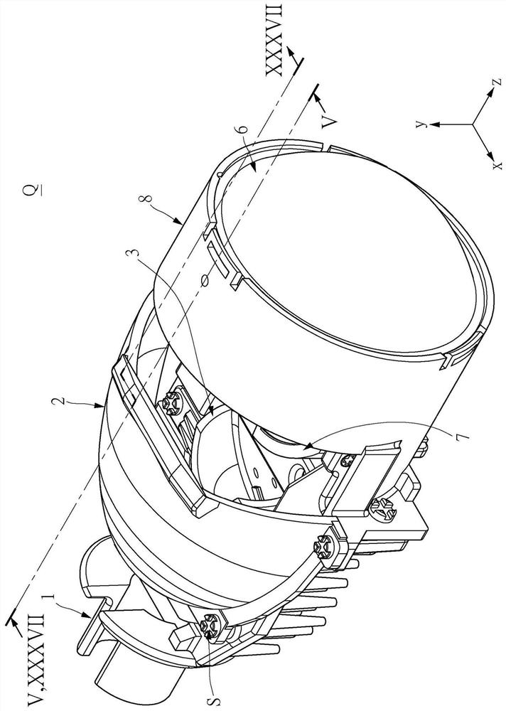
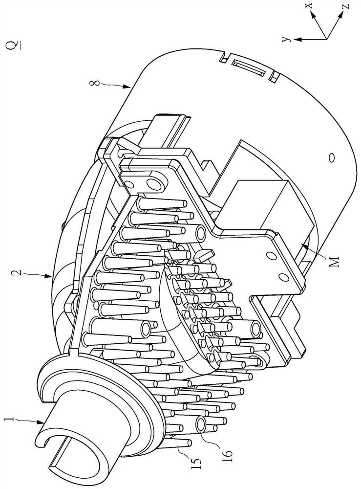
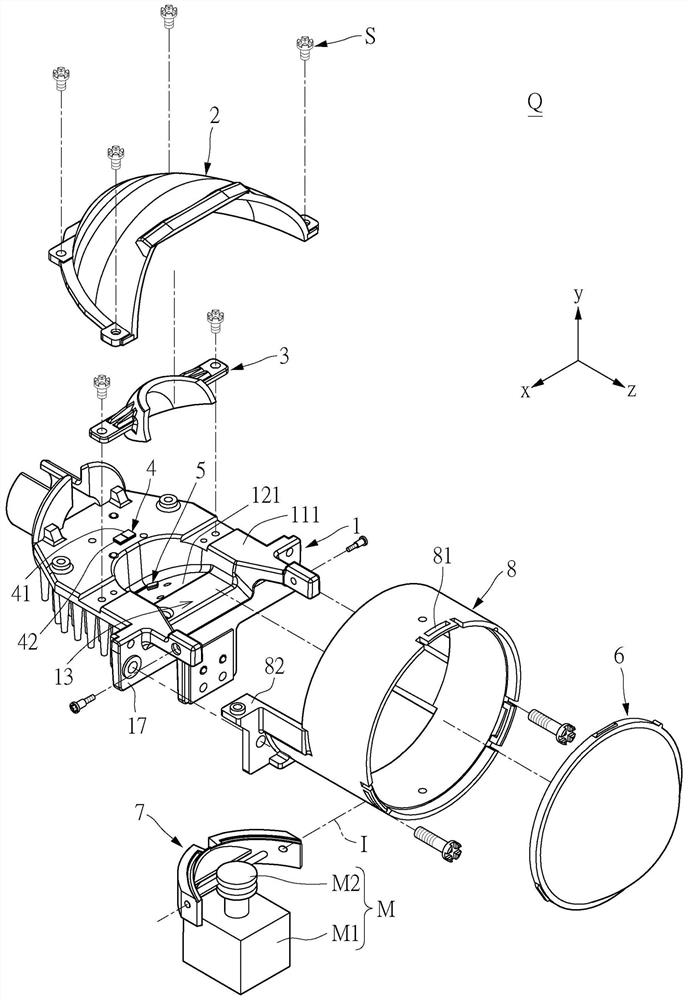
[0077] First, see Figure 1 to Figure 4 as well as Image 6 as shown, Figure 1 to Figure 4 They are respectively three-dimensional decomposition and three-dimensional combination schematic diagrams of the light projection device Q in the embodiment of the present invention, Image 6It is a schematic diagram of the main structure of the light projection device Q in the near light state. The present invention provides a light projection device Q, which includes a bearing base 1, a first reflective structure 2, a second reflective structure 3, a first light emitting structure 4, a second light emitting structure 5, and a lens structure 6 and a shroud structure 7 . For example, the first reflective structure 2 and the second reflective structure 3 can be composed of a plurality of curved surfaces with different curvatures or a single curved surface, for example, the reflective structures can be composed of curved surfaces based on ellipses. In addition, the first reflective s...
no. 2 example
[0095] First, see Figure 9 and Figure 10 as shown, Figure 9 and Figure 10 It is a schematic diagram of the shutter structure 7 according to the embodiment of the present invention. It should be noted that the shutter structure 7 provided in the second embodiment can be used to replace the shutter structure 7 provided in the first embodiment. The shutter structure 7 provided by the embodiment of the present invention is preferably applicable to the implementation when the second light emitting structure 5 is located below the optical axis A of the lens, or the second light emitting structure 5 is located below the optical axis A of the lens and the first light emitting structure 4 Located on or above the optical axis A of the lens. In other words, in terms of the light projection device Q provided in the first embodiment, the distance between the first focal point 3a of the second reflective structure 3 and the optical axis A of the lens is greater than the first focal ...
no. 3 example
[0102] First, see Figure 11 to Figure 14 shown, and in due course with the Figure 15 and Figure 16 As shown, the third embodiment of the present invention provides a shutter structure 7 that can be applied to the light projection device Q, by Figure 9 and Figure 11 The comparison shows that the biggest difference between the third embodiment and the second embodiment is that the shutter structure 7 provided by the third embodiment has a groove-shaped structure G relative to the shutter structure 7 as a whole. In addition, the third embodiment The first reflective surface 731 and the second reflective surface 732 of the provided shutter structure 7 can also be arranged substantially parallel to the optical axis A of the lens. In detail, the shutter structure 7 may include a front cutoff edge 71 , a rear cutoff edge 72 and a top surface 73 . The rear cut-off edge 72 and the front cut-off edge 71 are disposed corresponding to each other, and the top surface 73 can be con...
PUM
| Property | Measurement | Unit |
|---|---|---|
| absorbance | aaaaa | aaaaa |
Abstract
Description
Claims
Application Information
 - R&D
- Intellectual Property
- Life Sciences
- Materials
- Tech Scout
- Unparalleled Data Quality
- Higher Quality Content
- 60% Fewer Hallucinations
Browse by: Latest US Patents, China's latest patents, Technical Efficacy Thesaurus, Application Domain, Technology Topic, Popular Technical Reports.
© 2025 PatSnap. All rights reserved.Legal|Privacy policy|Modern Slavery Act Transparency Statement|Sitemap|About US| Contact US: help@patsnap.com