Supercharge Your Innovation With Domain-Expert AI Agents!

Optical fiber with function of image compensation

An optical fiber and image technology, applied in the direction of bundled optical fibers, etc., can solve the problems of dark images, light deflection, and unrepresentable images

Inactive Publication Date: 2019-08-06
TAIWAN FIBER OPTICS
View PDF12 Cites 1 Cited by
  • Summary
  • Abstract
  • Description
  • Claims
  • Application Information

AI Technical Summary

Problems solved by technology

[0009] In order to solve the problem of the presentation of the patterns affected by the end edges 71 in Figure 18, the industry has proposed the following Figure 23 Shown is a quadrilateral optical member 90, the optical member 90 directly obliquely cuts the part of the original end to form a hypotenuse 91, so as to avoid the problem that the image cannot be presented, but the plurality of optical fibers 92 constituting the hypotenuse 91 will like Figure 24 The disclosed oblique section of the optical fiber 92 produces the problem of light deflection, so that the image brightness is good when the user watches from point N (or point L), but the image will be dark when viewed from point O (or point M), and then Produces brightness differences in images

Method used


Image

  • Optical fiber with function of image compensation
  • Optical fiber with function of image compensation
  • Optical fiber with function of image compensation

Examples


Embodiment Construction

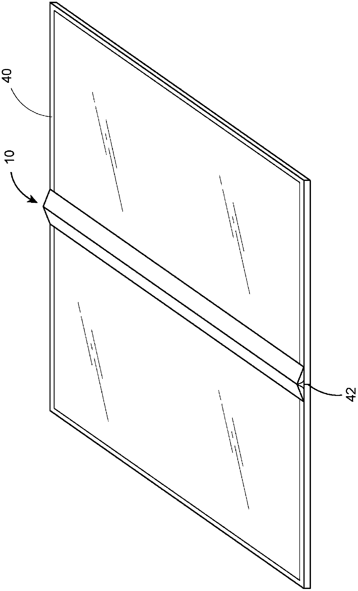
[0050] figure 1 It can be seen that the junction 42 of a frame where the two display devices 40 are placed close to each other is the non-effective area of ​​the image. The two optical components 10 are symmetrically arranged to cover the frame junction 42, so that the images of the display devices 40 can be refracted and presented at the frame junction 42 through the optical components 10, so that the images appear continuous. screen.

[0051] Figures 2 to 4 are one of the manufacturing methods of the optical component 10 of the present invention, first referring to Figure 2, a plurality of optical fibers 11 are arranged in the same direction and assembled into a bundle to initially form the optical component 10, and then pressure is applied to One of the surfaces of the optical member 10 makes it concave toward the other side; then, as shown in FIG. Cut down to the bottom end, so that the above-mentioned concave elongated block is divided into two elongated blocks with ap...


PUM


Abstract

Provided in the invention is an optical fiber with function of image compensation. The optical fiber comprises an optical member formed by combination of a plurality of fibers in same-direction arrangement. The optical member includes an output end surface, an input end surface and a lateral adjacent surface. The output end surface is formed by collection of cross sections of ends of the fibers, wherein the cross sections are in geometric shapes like perfect circles or regular polygons. The input end surface is formed by collection of cross sections of the other ends of the fibers, wherein thecross sections are in geometric shapes like perfect circles or regular polygons. The lateral adjacent surface extends in a same direction as the fibers. On the basis of the structure, the image displayed by the picture can keep the predetermined brightness no matter when the user watches the picture in a front or lateral direction.

Description

technical field [0001] The invention provides an optical fiber, especially an optical fiber with image compensation. The output end face of the transmission is tangent and the cross sections of multiple optical fibers formed are perfect circles or regular polygons. The input end face is obliquely cut and the polygon corresponding to the output end face appears Non-perfect circle or non-regular polygon, in order to maintain a certain brightness regardless of viewing the image from the front or side view. Background technique [0002] Fig. 13 and Fig. 14 are schematic diagrams of conventional optical fiber manufacturing methods and the specific application of the first embodiment. Fig. 13 firstly compresses an optical member 50 by a plurality of optical fibers 501 through pressure, and then obtains the optical member 50 in a triangular columnar shape by cutting as shown in Fig. 14 , the optical member 50 has an output end face 51, An input end face 52 and a side adjoining sur...

Claims


Application Information

Patent Timeline
Patent Type & Authority Applications(China)
IPC IPC(8): G02B6/06
CPCG02B6/06
Inventor 吕俊毅
Owner TAIWAN FIBER OPTICS
Features
  • R&D
  • Intellectual Property
  • Life Sciences
  • Materials
  • Tech Scout
  • Unparalleled Data Quality
  • Higher Quality Content
  • 60% Fewer Hallucinations
Learn More