
Circuit for reducing total harmonic distortion and increasing power factor

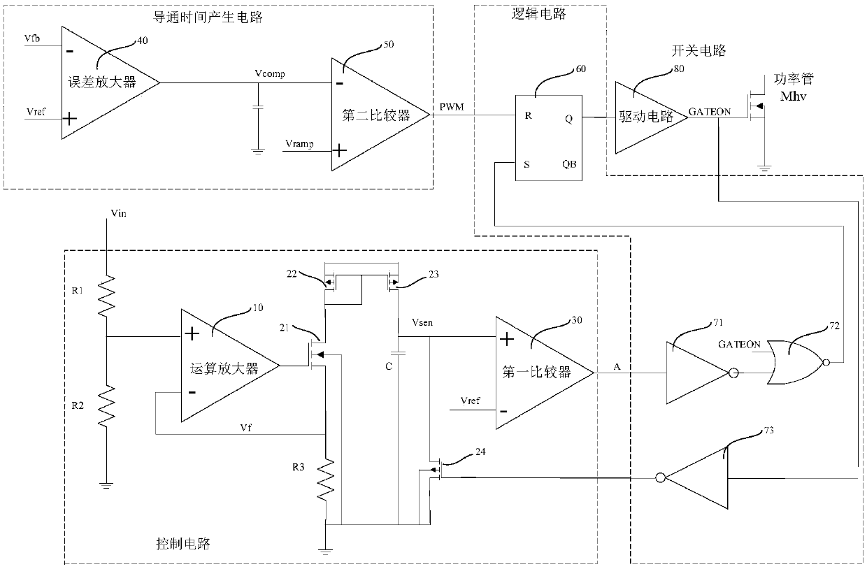
A technology for total harmonic distortion and power improvement, applied in the field of voltage source integrated circuits, which can solve the problems of low THD value, inability to achieve, and reduced duty cycle.

Pending Publication Date: 2019-08-06
上海权策微电子技术有限公司
View PDF0 Cites 0 Cited by
  • Summary
  • Abstract
  • Description
  • Claims
  • Application Information

AI Technical Summary

Problems solved by technology

However, the duty cycle D decreases with the increase of the circuit voltage Vin, and the average value Iav of the input current Iin is not proportional to the circuit voltage Vin
The active power factor correction circuit with a fixed on-time Ton only guarantees that the peak value Ipk of the instantaneous current I is proportional to the circuit voltage Vin, and cannot guarantee that the average value Iav of the input current Iin is proportional to the circuit voltage Vin, so the conventional technology Only the fixed on-time Ton is controlled, and a lower THD value cannot be achieved

Method used


Image

  • Circuit for reducing total harmonic distortion and increasing power factor

Examples


Embodiment Construction

[0023] In order to make the above objects, features and advantages of the present invention more comprehensible, specific implementations of the present invention will be described in detail below in conjunction with the accompanying drawings. In the following description, numerous specific details are set forth in order to provide a thorough understanding of the present invention. However, the present invention can be implemented in many other ways different from those described here, and those skilled in the art can make similar improvements without departing from the connotation of the present invention, so the present invention is not limited by the specific implementations disclosed below.

[0024] In the description of the present invention, it should be noted that the term "connection" refers to electrical connection.

[0025] Unless otherwise defined, all technical and scientific terms used herein have the same meaning as commonly understood by one of ordinary skill in...


PUM


Abstract

The invention discloses a circuit for reducing total harmonic distortion and increasing a power factor. The circuit comprises a control circuit, an on-time generation circuit, a logic circuit and a switching circuit, wherein the control circuit acquiring an input voltage Vin change to generate a time signal A and feeds the time signal A back to the logic circuit. The on-time Ton generation circuitgenerates a time signal PWM. When the input voltage Vin is high, the logic circuit determines that the time signal PWM fed back by the on-time Ton generation circuit is the on-time Ton. When the input voltage Vin is low, the logic circuit determines that the time signal A fed back by the control circuit is the on-time Ton. A delay time inversely proportional to the input voltage is generated at the input voltage valley to prolong the on-time, thereby reducing the total harmonic distortion and increasing the power factor of a voltage-source system.

Description

technical field [0001] The invention belongs to the field of voltage source integrated circuits, in particular to a circuit for reducing total harmonic distortion and improving power factor. Background technique [0002] In AC-DC power supply, fluorescent lamp drive, and LED drive systems, low power factor PF will cause harm to interference circuit voltage and increased system loss. In the prior art, it is improved by controlling the on-time Ton. [0003] The power factor PF is the ratio of active power to apparent power in the system, [0004] PF=P 有功功率 / P 视在功率 =cosα / (1+THD 2 )1 / 2, [0005] Among them, α is the phase difference between the current fundamental wave and the voltage signal, and THD is the total harmonic distortion. [0006] Low power factor PF will cause interference circuit voltage and increase system loss. The active PF correction circuit is widely used in power supply, fluorescent lamp drive, LED drive and other fields to realize the function of impro...

Claims


Application Information

Patent Timeline
IPC IPC(8): H02M1/08
CPCH02M1/08
Inventor 王鲁文徐鹤川徐刚
Owner 上海权策微电子技术有限公司
Learn More